(edit -- I originally said "wavelengths down to 1/46th.." Got wavelengths and frequency confused  )
)
I ran into this paper - broadband diffusors that work up to wavelengths 46x the thickness of the diffusor. Looks like it would be a feasible 3D print (in a number or sections to get to the 52 inch width).
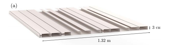
See in particular, page 7 and table 4. (The deginitions of the parameters in table 4 are shown in Figure 1).
https://www.ncbi.nlm.nih.gov/pmc/articles/PMC5511165/pdf/41598_2017_Article_5710.pdf
These could be made into wall hangings only a little over 1" thick and work down to 250Hz! Get some grille material the same color as the walls and should be an easy sell to significant others who would hate traditional diffusors. If I work up the STL files, I'll post them.
)I ran into this paper - broadband diffusors that work up to wavelengths 46x the thickness of the diffusor. Looks like it would be a feasible 3D print (in a number or sections to get to the 52 inch width).
See in particular, page 7 and table 4. (The deginitions of the parameters in table 4 are shown in Figure 1).
https://www.ncbi.nlm.nih.gov/pmc/articles/PMC5511165/pdf/41598_2017_Article_5710.pdf
These could be made into wall hangings only a little over 1" thick and work down to 250Hz! Get some grille material the same color as the walls and should be an easy sell to significant others who would hate traditional diffusors. If I work up the STL files, I'll post them.
Attachments

Last edited:
And here's the complication with that -- I made STL models for a 1ft high slice of this (in 11 prints of smaller parts to be combined) and the print time for that, with every speed up trick I could do, is still 28 hours. And that's with a 1mm nozzle and a 12"x12" bed. So, not a small project.
I may still do it, since my printer mostly sits there doing nothing most of the time. But to get to a 3ft x 4.5ft panel, its like four days of printing!

I may still do it, since my printer mostly sits there doing nothing most of the time. But to get to a 3ft x 4.5ft panel, its like four days of printing!
Attachments
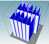
Yeah, and the structure doesn't look good for molding, or even extrusion for that matter. I'd be afraid of the overhanging wall things resonating. I put little bridge struts every 3 inches or so in the STL model to try to avoid that. Maybe some flat supports (or a screen?) could be attached to the top to keep it stable?
...Looks like it would be a feasible 3D print....
Looks to me like 5/4" board, nice 1/16" veneer plywood, a fine table-saw, and some glue and jigs. Rip a whole lot of 8mmX13mm etc-etc slats, the 100mm wide exposed faces, and start gluing to a 5mm backer.
Inconsistency is *good*. A series of resonances may plot well but the ear is harder to fool. Bumping the saw fence 1mm every few cuts will spread the resonances around.
You are right, structurally it "flaps". The resonator slots need little fillers every few inches. A few columns inside the larger resonators to support the faces.
I'm thinking that maybe a sheet of 'hardware cloth' (square grid largely open screen') could be glued across it to tame it all down, without too much added labor effort.
You might be right about using board strips, additional length is nearly 'free' (labor wise) doing that. Note that in the model the thickness of the walls is under a mm! I did them all at 1.2mm (about the thinnest I could get with a 1mm 3D printer nozzle). But I suspect that could be cheated substantially.
You might be right about using board strips, additional length is nearly 'free' (labor wise) doing that. Note that in the model the thickness of the walls is under a mm! I did them all at 1.2mm (about the thinnest I could get with a 1mm 3D printer nozzle). But I suspect that could be cheated substantially.
I think PRR has the right approach -- strips sliced on a table saw. Perhaps also make a bunch of little pedestals (back to 3d printing for those?) that could be placed where needed to help support the dangling sections and to break up resonances. I'd also 3D print small spacers to align all the parts for the right gap sizes.
It would be cool to use thin polycarbonate or lexan sheets for the stock material, but those can be tricky to cut (and tend to cut up your hands when handling the cut pieces!). It would be nice to have something available in ~4' length in one dimension. Open for ideas on cheap, easy to work with panels stock to do this with.
Sadly, in my living room, the place I'd most want to have one of these is behind our chairs, but there's a window there!
6mm plywood is probably a better structural bet for this application over MDF. Lauan would be tempting but even birch veneer isn't pricey in 6mm (~1/4" for us Yanks)
Depending on how Bill lays it out, there should be a good number of glued interfaces and structural brackets to keep everything solid. Finishing might be a huge pain!
Depending on how Bill lays it out, there should be a good number of glued interfaces and structural brackets to keep everything solid. Finishing might be a huge pain!
Another thread on this
https://www.diyaudio.com/forums/multi-way/360730-3d-printed-metamaterials-new-post.html with a correction to the Darko interview
https://www.diyaudio.com/forums/multi-way/360730-3d-printed-metamaterials-new-post.html with a correction to the Darko interview
So what's the verdict? Does it work?
Personally, I started to lose interest in it when I realized you should be able to get comparable results with a closed transmission line. And closed transmission lines can be simulated by Hornresp.
The main challenge there, is finding a tweeter where you can remove the back chamber. The Peerless DA25BFG08 is one.

- Status
- This old topic is closed. If you want to reopen this topic, contact a moderator using the "Report Post" button.
- Home
- General Interest
- Room Acoustics & Mods
- 3D Printed Metamaterials