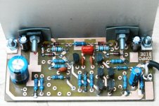
This general module, it can be used as Line or C.D. or Phono input, or as Line driver or as Buffer with some interchanges of the passive elements that contains; and for making filters in electronic X-overs. He is absolutely made with discrete devices, thus it can operate with a high level supply (in this case with +/- 26 Volts) with the benefits it offers this. For example it can drive a power amplifier even if it has Zin 1ÊÙ! And with unbalanced signal cables of big length (over 5 meters) because it masking the noise (don’t forget S/N ratio!) with enough dB and without loses due to extremely wide output signal and the ultra low Zout. Moreover the output is preloaded with an appropriate voltage divider to reduce the signal width in order it is avoided an overdrive of the next stage. Because a picture deserves thousand words, i quote below a photo of the trial module and some characteristic oscilograms.
Attachments
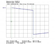
fotios said:2. Tilt of a 100 Hz square 6Vpp it is only 0,12V.
If you want to do advertising, at least know what you are talking about. The tilt of the square wave says nothing of the damping but shows that you either have capacitive in/out coupling or capacitive feedback coupling. It shows you the limit of lf response.
Jan Didden
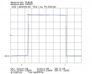
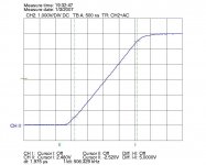
fotios said:3. Rise time of a 10 KHz square 6Vpp it is only 0,72 ìsec!! What an incredible speed!
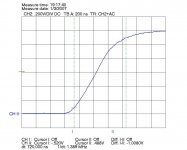
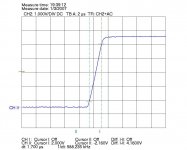
fotios said:4. Rise time of a 100 KHz square 5Vpp it is only 1,7 ìsec!!
This is less than 3V/uSec! Incredibly slow!
Jan Didden
Netlist said:In counterbalance, the PCB looks cute.
Care to post the schematic?
/Hugo
Good work, fotios!!! .... Hellas, Ellas, Ellada (greece)
I am interesting see your schematic, too.
Post please

I like discrete Line Preamplifiers & Buffers.
Much more fun to construct, than using those deadly boring op-amps chips.
( maybe we should call those
BLACK CHIP = Black Sheep
)If IC chips was better,
then Mr John Curl, Nelson Pass and Hugh AKSA Dean
and me lineup
wouldn't bother to design:
discrete amplifiers ... with transistors!
Welcome fotios, my southern European friend ... to our transistor amplifiers design GROUP
Looking forward to more info.
Regards
lineup
Lineup Discrete Audio Lab
I believe that you confuse the Rise Time with the Slew Rate. The Slew Rate is measured absolutely otherwise and not by the oscilogram that you saw. The Rise Time expresses the response speed in fast transient signals with compensated the Miller pole at VAS. Do not forget that this circuit operates with +/- 26 Volts = 52 Vpp. I confirm that if it operated with +/- 50 Volts = 100 Vpp the Rise Time would be roughly same, therefore for a square of 10 KHz would speak for a Voltage Slew Rate by far bigger than you calculated. From the other hand as we know the Slew Rate is not reported in who frequency it is measured. If i could to measure him – something that is impossible – with my scope (a HAMEG HM507) in a square of 100 Hz, the number would be incredible big. Unfortunately i do not have anything that it measures Slewing therefore i satisfy in the Rise Time that measures my oscilloscope. Moreover the signal generators that i have, they are simple function generators therefore put an error from the input in the circuit as these have limited Rise Time. In any case the Slew Rate does not mean something interest believes; he is simply something as the THD + noise for the consumers. For a designer of electronics is enough the Rise Time from as long as i see so much years. A designer can easily appreciate the possibilities of a given circuit from oscilograms such as that i quoted.janneman said:
This is less than 3V/uSec! Incredibly slow!
Jan Didden
Dear Jannemanjanneman said:
If you want to do advertising, at least know what you are talking about. The tilt of the square wave says nothing of the damping but shows that you either have capacitive in/out coupling or capacitive feedback coupling. It shows you the limit of lf response.
Jan Didden
I do not make any advertising, simply i am enthusiastic type. I was a lot glad from this construction. But it is not thus, i apologize also if you misunderstand me. This at least i understood from your reply. As for the damping you do not take him into account so much. I do not mean damping factor, as i suppose that you understood. The term damping i use for a lot of things, even of mechanic nature. Thus many times i express myself also in electronics with the same term. In any case the tilt of duty cycle of the pulse, it expresses damping as it is usually said, in the Greek we use also the word “erasure” as this means the same thing roughly. If we see now the given oscilogram and consider damping as quantity of time (something that does not abstain from the truth) if the duty cycle line forms an angle of 90° with the trailing edge of pulse, damping he would be smallest than the sloping line that appears in the figure (with the Pythagorean theorem as base or with a trigonometric function can be proved this). This precisely i mean when i say damping. That the pulse has very small tilt in so much low frequency as 100 Hz, that is to say it is erased very fast. Sure this has relation with those who writes in the remainder part of your reply. I hope to become comprehensible.
Friendly regards
Fotios Anagnostou
Sorry for the mistake. In this oscilogram the signal width is 1,2Vpp and not 6Vpp as reportedfotios said:3. Rise time of a 10 KHz square 6Vpp it is only 0,72 ìsec!! What an incredible speed!
AndrewT said:Hi,
can someone help me?
What is the definition of slew rate?
How does one measure slew rate?
Yes! Janneman is right! Maybe fotios can tell us how is he measuring slew rate??
Hi all
After a fast search:
For Slew rate definition
Here
A good article about slew rate measurements and explanation. Damping (presence of ringing after leading/trailing edge of square wave) is covered as well.
here
Another one
here
Please note that an oscilogram of the output alone, can not provide enough information. The oscilogram of the input has also to be provided. Alternatively, a differential output-input measurement (subtraction) can be used.
Some good info about differential measurements in general can be found
here
Lot of measurement set-up here (under “oscilloscopes” menu)
Regards
George
Rise time it is offered as a better evaluation method of the transient response of an amplifier because it is measured after the Miller dominant pole compensation. In an amplifier without Miller pole compensation, the rise time it is unbelievable small but with oscillations. On the other hand the slew rate remains the same in the two cases, with the Miller pole compensated or not. Slew rate can measured with or without closed loop (take a look for example in the description of LM833 in the National semiconductors page this I.C. referred with a slew rate of 7 V/ìs but in open loop) but rise time always with closed loop.AndrewT said:Hi Peranders,
thanks, but can you explain why Fotios and Janneman cannot agree on something that is so easily defined?
What am I missing between the two sides of the argument?
Dear gpapag
Dear George thanks for your precious suggestions. I hope to put an end in this conflict. I think we talk about the speed of an amplifier. Looking in my oscilograms what is your opinion about the speed of the presented preamp module? An amplifier is still fast with a rise time of 2 ìsec or with a slew rate of 200V/ìsec at the end.
Dear George thanks for your precious suggestions. I hope to put an end in this conflict. I think we talk about the speed of an amplifier. Looking in my oscilograms what is your opinion about the speed of the presented preamp module? An amplifier is still fast with a rise time of 2 ìsec or with a slew rate of 200V/ìsec at the end.
- Status
- This old topic is closed. If you want to reopen this topic, contact a moderator using the "Report Post" button.
- Home
- Amplifiers
- Solid State
- Wow!!! A wonderful preamplifier module!