I built this power supply and it's been working fine at 250W output power (build log is here).
I would like to scale it up to supply a pair of UcD400's (about +/-60V @ 8A). If I understand correctly, I need to:
1) Use a bigger core at a higher frequency (Currently it's an ETD39 @ 50kHz).
2) Obviously, change the turns ratio on the transformer. Referring to this site, for a minimum of 270V and maximum of 340V input and 100kHz, the transformer should be a ETD59 core with 29 (15+15) primary windings and 27 (14+14) secondary windings for a total of 120V output volts?
3) To save some trouble, I might not use the semi-synchronous rectification described in the original article. Instead, I will probably implement a standard fullwave bridge rectifier with a center tapped winding.
But then, adding a few more windings for the synchronous rectifiers probably isn't too difficult either...")
4) The FETs will have to be upgraded also, I see the maximum current through each FET is something like 9 amps.
Will the existing drive circuitry be able to properly drive bigger FETs?
Will any other (subtle) modifications (besides the obvious changing of OVP and regulation voltage dividers) be required?
Can the existing snubbers still be used successfully?
Thanks!
I would like to scale it up to supply a pair of UcD400's (about +/-60V @ 8A). If I understand correctly, I need to:
1) Use a bigger core at a higher frequency (Currently it's an ETD39 @ 50kHz).
2) Obviously, change the turns ratio on the transformer. Referring to this site, for a minimum of 270V and maximum of 340V input and 100kHz, the transformer should be a ETD59 core with 29 (15+15) primary windings and 27 (14+14) secondary windings for a total of 120V output volts?
3) To save some trouble, I might not use the semi-synchronous rectification described in the original article. Instead, I will probably implement a standard fullwave bridge rectifier with a center tapped winding.
But then, adding a few more windings for the synchronous rectifiers probably isn't too difficult either...
4) The FETs will have to be upgraded also, I see the maximum current through each FET is something like 9 amps.
Will the existing drive circuitry be able to properly drive bigger FETs?
Will any other (subtle) modifications (besides the obvious changing of OVP and regulation voltage dividers) be required?
Can the existing snubbers still be used successfully?
Thanks!
1.) Maybe you need bigger core, but not as big as ETD59. It depends on how much wire will you try to put in, as for power, ETD44 can put over 1kw at freq. 50~100kHz.
2.)At input of 270v freq 50kHz, turn ratio would be PRI = 1.4xSEC
I put 90v for sec votage since this page calculates for unregulated supply.This way you can have it regulated.
3.)Best and simple
4.)9A x Vin/2 = 1.4kW+!!. Try to get IRF450, since they are the best for their price, at least for me
If you are using original gate trafo that was made to drive NPN tran., it will NOT work with fets.
Snubbers will still be useful if you use the same freq., I think
Thanks for the guide..
I have a pair of IRFP264's lying around (250V / 38A / Rds = 0.075ohm), these should do as the half-bridge voltage is only 170V (with 340V DC side voltage)?
I am using a re-wound gate driver transformer with 26 turns on primary (to the SG3525) and 16+16 turns on the secondary (to the FETs). This should give me slightly more than 10 volts to drive the MOSFET gates...
I will probably be rewinding another gate transformer using an RM core... these are much less hassle than trying to strip the windings from the old transformers
4.)9A x Vin/2 = 1.4kW+!!. Try to get IRF450, since they are the best for their price, at least for me
If you are using original gate trafo that was made to drive NPN tran., it will NOT work with fets.
I have a pair of IRFP264's lying around (250V / 38A / Rds = 0.075ohm), these should do as the half-bridge voltage is only 170V (with 340V DC side voltage)?
I am using a re-wound gate driver transformer with 26 turns on primary (to the SG3525) and 16+16 turns on the secondary (to the FETs). This should give me slightly more than 10 volts to drive the MOSFET gates...
I will probably be rewinding another gate transformer using an RM core... these are much less hassle than trying to strip the windings from the old transformers
luka said:
Snubbers will still be useful if you use the same freq., I think
I'm probably going to go up to 100kHz... the snubbers on the primary side are 100 ohms + 2.2nF and those on the secondary side are 10 ohm + 10nF. Will these still be usable?
megajocke said:You will have full DC bus voltage over the transistor when the other one is conducting. So you need FETs with a higher voltage rating.
So I might have to get IRFP460's or something...
I have seen this project and would like to build it. If you're going to go for 120V (+/-60V) @ 8A (close to 1kW), I would give the Full-Bridge topology some serious consideration. Yes, the half-bridge is good for 200-1000W, and, yes, it is simpler to implement, but you will have less drain currents through the MOSFETs and lower primary-side current in the main Xfmr with the fullbridge. Not to mention, capacity to expand the power levels.
Steve
Steve
N-channel,
Go for it! Winding new transformers isn't difficult and it's guaranteed that they will be at least the correct physical size (some of those AT psu's have such a small main transformer that I'm quite suspicious of them!).
Just one point, I would use (at least) 200V rated polypropylene capacitors in the snubbers (C5 and C8). This point isn't really clear in the text.
For the fullbridge design, am I correct in saying that I just need to put 4 windings on the driver transformer instead of just 2?
Then each pair of the driver windings will go to opposite legs of the transistors?
simingx,
Don't tempt me! I need another unfinished project like a hole in the head! Seriously though, you are correct in your understanding that four separate windings will be needed for the secondary side of the driver Xfmr. I agree with you on the 200V rating for the snubbers. Probably not necessary, but better to be safe.
As for transformer core size from all those AT & ATX boxes, here is a dirtly little secret every manufacturer of all these standard (and fancy 500W & up) boxes don't tell ya': for a 200-250W rated PSU, the core is good for only about 60-70W continuous and 200-250W on a time-limited basis. This notion is predicated on the idea that, for powering loads with a wide dynamic range (such as disk drive motors and gain-card amplifiers) the power supply will see full power levels for only a second or two, and not continuously.
If you crack open some older AT boxes, I mean like first-generation ones, you will find that the cores are at least twice the size as those found in contemporary boxes. Couple o' reasons for this: 1) Efficiencies got better, eliminating the need for oversized components, and 2) smaller parts were cheaper, and, for the most part, could do the job as well.
Steve
Don't tempt me! I need another unfinished project like a hole in the head!
Seriously though, you are correct in your understanding that four separate windings will be needed for the secondary side of the driver Xfmr. I agree with you on the 200V rating for the snubbers. Probably not necessary, but better to be safe.As for transformer core size from all those AT & ATX boxes, here is a dirtly little secret every manufacturer of all these standard (and fancy 500W & up) boxes don't tell ya': for a 200-250W rated PSU, the core is good for only about 60-70W continuous and 200-250W on a time-limited basis. This notion is predicated on the idea that, for powering loads with a wide dynamic range (such as disk drive motors and gain-card amplifiers) the power supply will see full power levels for only a second or two, and not continuously.
If you crack open some older AT boxes, I mean like first-generation ones, you will find that the cores are at least twice the size as those found in contemporary boxes. Couple o' reasons for this: 1) Efficiencies got better, eliminating the need for oversized components, and 2) smaller parts were cheaper, and, for the most part, could do the job as well.
Steve
I did do that... but it seems not fast enough to protect the FETs against short circuit (it works for overload by sending the circuit into some sort of "current limit" mode, I'm not sure whether it's supposed to work like that?).
And I'm not very excited about trying that little "experiment" again..
And I'm not very excited about trying that little "experiment" again..
Is not fast enough?! I think it is faster then fuse blowing up... I seen a lot of supply that have let say 105% current limiting, but if current goes to 130% then it shuts down.
Where did you put your current trafo in your design?
If it did work for overload, it must have been working for short circuit, since in both cases is intended to use more current then wanted.
There must have been any other type of error to blow up your mosfets or your current limiting didn't work.
Where did you put your current trafo in your design?
If it did work for overload, it must have been working for short circuit, since in both cases is intended to use more current then wanted.
There must have been any other type of error to blow up your mosfets or your current limiting didn't work.
I've been doing a lot of learning for something like this too, I have a schematic for a full bridge but not sure if it will work.
I was tring to desgin this so it can run off of the TL494, the SG3525 should work too, I have to premaid drive transformers for fets that I robed out of a cooked server PSU.
I was tring to desgin this so it can run off of the TL494, the SG3525 should work too, I have to premaid drive transformers for fets that I robed out of a cooked server PSU.
Attachments
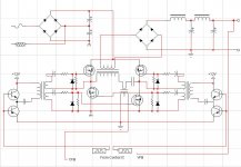
May be a stupid question, but I'm still learning here, What have I put in?
I was tring to find some pictures Eva posted for different turn on and off circuit for Bipolars and fet but the search function on this fourm hates me today, do you know where they are?
Also what is more of a problem slow turn on or slow turn off? (or both)?
Thanks Dave.
BTW the schematic I posted is for 120V mains getting x2 by caps, remove link from bridge to center of caps for 240V operation.
Well as I understand that is both.Some what slower turn on is good for core saturation, since fast turn off is good all the time I think.What you have put is: For turn off mosfet gate is discharged through resistor and trafo.If there is leakage inductance in trafo, mosfet will not discharged fully, what could result in destruction of fets or high heat.But if you use that shema the fet is turnd on slowly(resistor), but turnd off fast with transistor.
As for pictures: Eva have deleted them from her server, and I have only that shema of what there was.
As for pictures: Eva have deleted them from her server, and I have only that shema of what there was.
- Status
- This old topic is closed. If you want to reopen this topic, contact a moderator using the "Report Post" button.
- Home
- Amplifiers
- Power Supplies
- Built a 250W SMPS, possible to modify?