Hi, stumbled upon this forum that the Eidetic GB2a and GB2b pre and power amplifier which I owned is built by non other than Amplifierguru!
Eidetic GB2a and GB2b are superior by today standards in terms of performance.
The amps delivers with clarity, focus, and natural dexterity that equals or surpasses many high end audio brands which I have auditioned in the likes of Krell and Classe. What impresses me is the richness and warmness of music vocals. The bass is deep and extended. No fatigue signs after long listening. These amps have serve me very well all these years.
I reckon that Amplifierguru has put a lot of sciences in these amps and the sciences simply works, and unknown to many!
Good job Amplifierguru!
Well thanks direstraits - You are one of only 4 owners in Singapore and it's very rewarding to know my effort is being appreciated and the design exceeds expectations - to this day!
Hi Andrew T,
The design was a two loop nested feedback using an OPA627 front end driving a discrete comp differential/Vas/EF using 3 pair of Toshiba 2SK405/J115. The chip supplies were driven from the main rails using TL431 and BJT current sources down to 15V zeners bypassed. The nested loop was capacitative, rolling off to below unity at HF resulting in a single pole main loop response for stability. The transformer was 300VA with 20,000uF (8 x 2,500uF) per side shared C in the common PS.
The design owed a lot, I believe, to the enormous PSRR resulting from the chip gain before intrusion, and less to the near zero THD and IM. The design was DC coupled with no direct signal path C's.
These are design traits I have maintained in the Simple Killer Amp by introducing the new topology for better PSRR in the discrete section and it resulting in such low THD, as stated on my website intro, I felt it was a simple design that delivered.
Cheers,
Greg
")
Hi Andrew T,
The design was a two loop nested feedback using an OPA627 front end driving a discrete comp differential/Vas/EF using 3 pair of Toshiba 2SK405/J115. The chip supplies were driven from the main rails using TL431 and BJT current sources down to 15V zeners bypassed. The nested loop was capacitative, rolling off to below unity at HF resulting in a single pole main loop response for stability. The transformer was 300VA with 20,000uF (8 x 2,500uF) per side shared C in the common PS.
The design owed a lot, I believe, to the enormous PSRR resulting from the chip gain before intrusion, and less to the near zero THD and IM. The design was DC coupled with no direct signal path C's.
These are design traits I have maintained in the Simple Killer Amp by introducing the new topology for better PSRR in the discrete section and it resulting in such low THD, as stated on my website intro, I felt it was a simple design that delivered.
Cheers,
Greg
Attachments

amplifierguru said:The design was a two loop nested feedback using an OPA627 front end driving a discrete comp differential/Vas/EF using 3 pair of Toshiba 2SK405/J115.
One loop on the opamp, the second feedback loop on the differential i suppose ?
I take it the signal to the differential was from the output of the OPA627, not from the supply lines of the chip as Sphinx amplifiers did overhere ?
(AD opamp-6 Hitachi Mosfets)
(striking that the Siltech boys did acrylic fronts on their amps too in those same years)
Any chance of a schematic of the Greg Ball 2B ?
Attachments
Hi Andrew T,
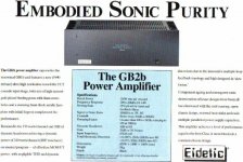
The brochure actually stated <0.05% 20Hz -20KHz into 1 Ohm.
The transformer had 4 x 24V secondary windings which were in series for 4-8 ohm operation (99.9% in practice) and in parallel pairs for 2 x 24V peak rectified to +/-34V for 2-1 Ohm use! that way power levels were 150W -200W for all loads.
Hi Jacco,
The design format is shown attached and has since been patented by someone else (US patent 6201442) six years after it was published in my product design paper in Australian Hi Fi and presumably copyright.
Regarding appearance, the original product (GB1b) was in 1989 and used an LF357 and it's appearance was, at best functional, having the same mesh front as the top. I added the acrylic faceplate at the same time the OPA627 was released, my wife and I auditioned it and had to include it! I don't know of Siltech - what is that? I had reworked a few Meridian DACs that had shiny fronts though. I tried the supply line chip feed but I could never get it to sound any good.
Cheers,
Greg
The brochure actually stated <0.05% 20Hz -20KHz into 1 Ohm.
The transformer had 4 x 24V secondary windings which were in series for 4-8 ohm operation (99.9% in practice) and in parallel pairs for 2 x 24V peak rectified to +/-34V for 2-1 Ohm use! that way power levels were 150W -200W for all loads.
Hi Jacco,
The design format is shown attached and has since been patented by someone else (US patent 6201442) six years after it was published in my product design paper in Australian Hi Fi and presumably copyright.
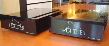
Regarding appearance, the original product (GB1b) was in 1989 and used an LF357 and it's appearance was, at best functional, having the same mesh front as the top. I added the acrylic faceplate at the same time the OPA627 was released, my wife and I auditioned it and had to include it! I don't know of Siltech - what is that? I had reworked a few Meridian DACs that had shiny fronts though. I tried the supply line chip feed but I could never get it to sound any good.
Cheers,
Greg
Attachments
Hi Amp guru,
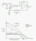
looking at your last post & gain plot.
Can you explain how you determine suitable values for the local feedback cap around the power amp and then the parallel cap in the global feedback path.
Can you also explain the gain plot at the hi freq end where the slope changes from 12db back to 6db/oct. Is this the global cap working for you? Is this necessary to ensure overall stability where slope <9db/oct as it crosses the 0 db gain?
Hi Andrew,
excellent questions!
Here goes.
The discrete section was seperately stabilised so it was UGS - using equal input and feedback R's and sq wave test trimmed with diffl emitter resistors so no Vas comp was needed. Once this was done a feedback C was selected such that the discrete FB loop gain permitted full output -3dB at 100KHz from maximum chip drive i.e. +/- 13V at the discrete input resistor. Values were, I think, 4K7 and 150pF.
Then the main loop was closed around the chip and output stage using a FB rolloff at 160KHz (27K//33pF) and the same as the input filter (1K//1000pF). Thus there was a 12dB /octave filtering at HF. The input/output transfer function rolled off at 6dB/octave faster than the internal loop.
As you see with the FB loop rolloff (6dB /octave) and open loop rolloff (12dB/octave) they cross at approx 6 dB above the feedback zero caused by the input leg R and the feedback C (1K, 33pF). The whole arrangement is a 2pole nested loop satisfying nyquist requirement of closing (relative) at 6dB/octave with an extra 22degrees margin from the FB zero. A 15 turn on 1ohm 1W zobel was used and stability was exemplary. I may have included an inner loop FB zero stopper R of about 150R.
Follow that?
It doesn't cross 0dB gain - the two intersect before that.
Cheers,
Greg
Fair enough.
I designed this without any sim - just on paper with my calculator and didn't build a prototype. Straight to 100 production run. Worked like a bought one, only better. My first MOSFET amplifier.
The new topology loses very little output volts so can achieve the same output from 6V less supply which, for the same VA transformer is about 8% more current rating, one step down in C voltage rating and less dissipation.
Audibly, I expect very little, if any, discernable difference between the two, and both have excellent stability. No heatsinked Vas drivers this time so simpler assembly.
Cheers,
Greg
- Status
- This old topic is closed. If you want to reopen this topic, contact a moderator using the "Report Post" button.
- Home
- Amplifiers
- Solid State
- Eidetic by Amplifierguru