All,
this thread is a split-off from the DIY TT thread and meant to harbour all discussions concerning
motor, motor PS, platter speed measurements.
I start right now with platter speed measurements for platter drives not having a speed regulator with quartz reference.
Somewhen in the next weeks, some of you will get their maxon DC motor from me and i cannot give you exact voltages for exact speeds, only rough guesses. But we have to get the speed precisely on the value; most of you will find they are quite sensitive AFA PRaT in connection with wrong speed is concerned.
The easy and precise way to measure platter speed is to use a repeating flashlight flash at a strobe disk having a bar pattern and lying on top of the platter: a stroboscope.
The flashlight has a fixed 120Hz flash frequency and a very short duty cycle, say, less than 5%. Means: the light is on 5% of the time only. The shorter the better.
Strobe disk:
The strobe disk has the right count of (usually radially oriented) bars in equal angular spacing so that at proper speed, the angular progression time between two bars is exactly equal to the fixed flash frequency. Then the bar pattern appears to stand still; if the platter speed is higher, the pattern slowly rotates clockwise, if lower, the pattern rotates counterclockwise.
Formula for bar count: 120*60/speed
Right count for:
33.33 rpm: 216 bars
45rpm: 160 bars
78.26 rpm: 92 bars
The strobe disk can be drawn and printed with any CAD program able to create polar element arrays. Any shape of the bar will do, even dots or the number 33 or 45 works fine: just rotate the pattern element the right count of times in equal angular spacing.
One problem: how to cut the hole for the platter spindle into the strobe disc and not cut it too small, too big, too excentric? A hard task w/o fancy optical and mechanical aids.
My work-around for this problem: Radius of the platter spindle is 3.6mm. Lets assume we use a bit more stiff and heavy-weight paper.
Please use a scalpel and make a vertical straight cut in 3.6 mm distance from the center haircross in 03:00 position. Then make a horizontal straight cut in 3.6 mm distance from the center haircross in 06:00 position. Cuts should intersect. Now you can carefully round-bend a dog-ear upwards. Do not bend the dog-ear sharply.
The dog ear will act as a spring pushing the spindle against the straight edges, allowing no play and not clamping the template as a too small circular hole would do. As the hole is triangular (hence not airtight), the strobe disc will not suck itself on the platter surface. This workaround is good for a strobe disc but also for any tonearm adjusting templates.
Strobe flashlight:
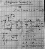
I decided to use a quartz-stabilized oscillator triggering a monoflop with 250µsec pulse width; this pulse drives a transistor switching a green LED with 11 candela @30mA. This is constant current rating, so the pulse current can be considerably higher without destroying the LED. I made the experience that beyond 200mA, such a LED won't increase in brightness, so 150-200 mA pulse current are a wise choice.
Of course, the flashlight could be made using a 555 timer and a driver trasistor, but this circuit will not have inherent frequency stability and it must be tuned to right frequency. And on later re-check, frequency may be not on track.
Been there, done that.
An easy way to make such a flashlight is using a 3.93216 MHz quartz and divide this frequency by 2^15(=327678). CD4060 is a CMOS chip having the oscillator and a binary divider of up to 2^14 onboard. I use a CD4013 (2x D-flop) for another division by 2 and for the monoflop.
A quartz, two cheap CMOS chips, a driver transistor and some resistors and pF caps, and an expensivish green LED, that's all. IF the oscillator oscillates at all, it does so at exactly 120Hz.
I build one as as soon as it works, i post circuit and details.
this thread is a split-off from the DIY TT thread and meant to harbour all discussions concerning
motor, motor PS, platter speed measurements.
I start right now with platter speed measurements for platter drives not having a speed regulator with quartz reference.
Somewhen in the next weeks, some of you will get their maxon DC motor from me and i cannot give you exact voltages for exact speeds, only rough guesses. But we have to get the speed precisely on the value; most of you will find they are quite sensitive AFA PRaT in connection with wrong speed is concerned.
The easy and precise way to measure platter speed is to use a repeating flashlight flash at a strobe disk having a bar pattern and lying on top of the platter: a stroboscope.
The flashlight has a fixed 120Hz flash frequency and a very short duty cycle, say, less than 5%. Means: the light is on 5% of the time only. The shorter the better.
Strobe disk:
The strobe disk has the right count of (usually radially oriented) bars in equal angular spacing so that at proper speed, the angular progression time between two bars is exactly equal to the fixed flash frequency. Then the bar pattern appears to stand still; if the platter speed is higher, the pattern slowly rotates clockwise, if lower, the pattern rotates counterclockwise.
Formula for bar count: 120*60/speed
Right count for:
33.33 rpm: 216 bars
45rpm: 160 bars
78.26 rpm: 92 bars
The strobe disk can be drawn and printed with any CAD program able to create polar element arrays. Any shape of the bar will do, even dots or the number 33 or 45 works fine: just rotate the pattern element the right count of times in equal angular spacing.
One problem: how to cut the hole for the platter spindle into the strobe disc and not cut it too small, too big, too excentric? A hard task w/o fancy optical and mechanical aids.
My work-around for this problem: Radius of the platter spindle is 3.6mm. Lets assume we use a bit more stiff and heavy-weight paper.
Please use a scalpel and make a vertical straight cut in 3.6 mm distance from the center haircross in 03:00 position. Then make a horizontal straight cut in 3.6 mm distance from the center haircross in 06:00 position. Cuts should intersect. Now you can carefully round-bend a dog-ear upwards. Do not bend the dog-ear sharply.
The dog ear will act as a spring pushing the spindle against the straight edges, allowing no play and not clamping the template as a too small circular hole would do. As the hole is triangular (hence not airtight), the strobe disc will not suck itself on the platter surface. This workaround is good for a strobe disc but also for any tonearm adjusting templates.
Strobe flashlight:
I decided to use a quartz-stabilized oscillator triggering a monoflop with 250µsec pulse width; this pulse drives a transistor switching a green LED with 11 candela @30mA. This is constant current rating, so the pulse current can be considerably higher without destroying the LED. I made the experience that beyond 200mA, such a LED won't increase in brightness, so 150-200 mA pulse current are a wise choice.
Of course, the flashlight could be made using a 555 timer and a driver trasistor, but this circuit will not have inherent frequency stability and it must be tuned to right frequency. And on later re-check, frequency may be not on track.
Been there, done that.
An easy way to make such a flashlight is using a 3.93216 MHz quartz and divide this frequency by 2^15(=327678). CD4060 is a CMOS chip having the oscillator and a binary divider of up to 2^14 onboard. I use a CD4013 (2x D-flop) for another division by 2 and for the monoflop.
A quartz, two cheap CMOS chips, a driver transistor and some resistors and pF caps, and an expensivish green LED, that's all. IF the oscillator oscillates at all, it does so at exactly 120Hz.
I build one as as soon as it works, i post circuit and details.
If going the quartz oscillator route, there is no need to use 120Hz as your base frequency. Easiest source for cheap x-tals are 32.768kHz watch x-tals. These can be divided down to any convenient power of 2. The formulas of Dice are usable for any base frequency if you substitute your frequency for the 120Hz.
dice45 said:An easy way to make such a flashlight is using a 3.93216 MHz quartz and divide this frequency by 2^15(=327678). ....
Bernhard, have you ever thought about of some small 8-pin microcontroller?
1. PIC 12Cxx or AVR ATTiny12 (cheap) If you don't have stuff for programmning I can be at your service.
2. No crystal! Built in oscillators are _very_ good but it doesn't harm to use a crystal.
3. LED
4. Plus output to a PLL.
The LED: I'm not totally sure about higher current -> stronger light. You come to certain point when the light don't get brighter. I don't know if it is only because of the heat or something else.
I have been a real analog guy but recently I have started to like microcontrollers a lot. You can do so many nice things with them especially when it comes to generate pulses and detect pulses, like in your case. You can even create a PLL also with software.
And while we're at it: You need detection of the speed also. Check for opto readers LED + phototransistor together. Works nicely if you have strobo pattern on the platter.
peranders,
agreed, PIC would be fine if someone does it. I have no PIC experience, i am a Motorola µC person and if pain is enough, by friend MHuber can convince me to forget motorola and use a hypermodern ATMEL which has everything onboard except a coffee warmer. But you won't get me using PICs. There are small areas of unconvincible prejudice in me, this is one of them. Rather use a 8051 or 8080.
Havoc,
you are right, but i had those 32kHz watch Xtals in my hand; they are huge. I want to have a neat lil thing, maybe even SMT-CMOS piggy-back on the Xtal and p2p wired and no PCB. And i want to have it right now. I want to be able to add a kit to the maxon motors ordered to anyone who asks how to measure platter speed and is willing to refund component costs.
I am completely sure on can come up with a smarter solution, no Q, but i wanted to be able to do it quick'n dirty, not even muse how to avoid the RC timeconstant needed for the monoflop.
And i want to provide it right now. I consider this as a secondary war scenario, low priority but nasty and necessary right now. I bought the components already.")
As soon as it works i post schematic and pix and anyone can have or leave it and build a better version
before i forget it: i used Amercian 120Hz as this is the only reasonable frequency i could find giving integer counts of bars for all three popular platter speeds. And even if someone is unbale to print a strobe disk himself, he can order 60/120Hz version from US websites.
agreed, PIC would be fine if someone does it. I have no PIC experience, i am a Motorola µC person and if pain is enough, by friend MHuber can convince me to forget motorola and use a hypermodern ATMEL which has everything onboard except a coffee warmer. But you won't get me using PICs. There are small areas of unconvincible prejudice in me, this is one of them. Rather use a 8051 or 8080.
Havoc,
you are right, but i had those 32kHz watch Xtals in my hand; they are huge. I want to have a neat lil thing, maybe even SMT-CMOS piggy-back on the Xtal and p2p wired and no PCB. And i want to have it right now. I want to be able to add a kit to the maxon motors ordered to anyone who asks how to measure platter speed and is willing to refund component costs.
I am completely sure on can come up with a smarter solution, no Q, but i wanted to be able to do it quick'n dirty, not even muse how to avoid the RC timeconstant needed for the monoflop.
And i want to provide it right now. I consider this as a secondary war scenario, low priority but nasty and necessary right now. I bought the components already.
As soon as it works i post schematic and pix and anyone can have or leave it and build a better version
before i forget it: i used Amercian 120Hz as this is the only reasonable frequency i could find giving integer counts of bars for all three popular platter speeds. And even if someone is unbale to print a strobe disk himself, he can order 60/120Hz version from US websites.
dice45 said:peranders, agreed, PIC would be fine if someone does it. I have no PIC experience,..
I have a PIC program more or less ready. If you hate PIC I can fix an ATMEL program instead. I have very little experience about AVR but my collegue is a real AVR nerd. (He thinks PIC is pure crap and AVR is gods gift to the mankind... He has a point, I have made a large PIC program, PIC is like MS, not too god but everyone uses it...therefore it must be good)

If you could give me a sketch over the whole concept including the PLL I could see what I could do about it. Send it privately if you want by I don't mind if it's a joint venture.
There is nothing wrong with normal 50 Hz light except the fact that I think it is rarely 50 Hz. I think it is not only rarely 50 Hz but also varies during the day according to power demand on the line network. So in the wee hours of the morning you might play everything a little fast and in the evening a little slow...
The solution thus is something not relying on the mains frequency.
/UrSv
The solution thus is something not relying on the mains frequency.
/UrSv
50Hz is more stable than you think. It has to be. These days with internationally coupled networks, 50Hz has to be 50Hz. It would not surprise me if these guys are as well locked to the timing standards as television broadcasters.
But it more difficult to work digitally with 50Hz than with something like 32.768kHz or higher. In the digital world 50Hz is an eternity, and dividing by 5 is not as straightforward as dividing by 2.
But it more difficult to work digitally with 50Hz than with something like 32.768kHz or higher. In the digital world 50Hz is an eternity, and dividing by 5 is not as straightforward as dividing by 2.
Havoc said:50Hz is more stable than you think. It has to be. These days with internationally coupled networks, 50Hz has to be 50Hz. It would not surprise me if these guys are as well locked to the timing standards as television broadcasters.
This isn't so simple. When the load is heavy, you will get a little bit lower frequency. You would notice this if you have a clock with synchrone motor. I have a hunch of that "mains speed" is a complicated thing, not just to lock the mains to a reference.
My opinion here is that it's of no importance at all to have a quartz reference but this is "overkill" (a little bit better than avarage) and also if dice45 will use a DC motor it's necessary with some sort of reference. After all a normal crystal is only 1 USD.
You will want to use an XTAL or
ceramic resonator since an RC oscillator will have greater temperature sensitivity.
lots of ways to monitor speed, and a strobe really isn't necessary if you can deploy a Hall effect sensor -- assuming the platter can be fashioned with teeth, or a gear can ge attached to the shaft of the motor,
you can measure the back EMF of certain motors to control torque, but I think that the larger problem wrt speed is that due to ambient voltage level changes, since the mass of the platter, hence its momentum, is so large relative to the force exerted by the stylus (heresy to the Linn folks, but for their theory to work you would have to epoxy the disk to the platter -- of course this didn't prevent me from buying that special power supply for my LP-12.) I fully expected to be corrected on this bit of albigensianism.
Re: You will want to use an XTAL or
Have you checked the stability of the built in RC-oscillators in PIC or AVR?
They are rather good! And also calibrated from factory. My experience is that they are surprisingly good.
jackinnj said:ceramic resonator since an RC oscillator will have greater temperature sensitivity.
Have you checked the stability of the built in RC-oscillators in PIC or AVR?
They are rather good! And also calibrated from factory. My experience is that they are surprisingly good.
All,
my post yesterday was notr meant to tqlk anone ou of trying anything. Sorry if it arrivede that way. A tiny µC is a very good idea. even if it is a PIC. I may try it out myself with a Motorola 68705 K1 (16pin); i have an incircuit emulator and programming system for that thing.
The CMOS oscillator was not as easy for me as i thought, out of training in this digital stuff; i have it working but spent almost a day with a intermittently faulty chip confusing me. I got a new chip and have atleast the oscillator running stable now.
60Hz/50Hz: (=100Hz/120Hz):
depends on which strobe disc you have.
both works.
But only 60Hz gives three integer bar counts for 33, 45, 78.
A light bulb runs on AC usually. Each **half** wave the brightness varies. If you use your room light, yo have a very faint and unsharp bar pattern image as the duty cycle of a lamp operated from AC is 50% ore more as the lamp filament glows longer tan currewnt is flowing.
The oscillator i am suggesting has 3-5% duty cycle. Means: the bar pattern image
has a very high contrast and is sharp and bright.
Havoc, yes you are right, 50Hz from the wall outlet are amazingly stable on the long run but not over the whole day. At e.g. 13:00 when lunch time is over and the factory in the neighbourhood start their machines, i can measure considerable variations. Not my only concern, see above. And you are right with the watch clock, just, my supplier does not have those crystals in his catalogue.
my post yesterday was notr meant to tqlk anone ou of trying anything. Sorry if it arrivede that way. A tiny µC is a very good idea. even if it is a PIC. I may try it out myself with a Motorola 68705 K1 (16pin); i have an incircuit emulator and programming system for that thing.
The CMOS oscillator was not as easy for me as i thought, out of training in this digital stuff
; i have it working but spent almost a day with a intermittently faulty chip confusing me. I got a new chip and have atleast the oscillator running stable now.60Hz/50Hz: (=100Hz/120Hz):
depends on which strobe disc you have.
both works.
But only 60Hz gives three integer bar counts for 33, 45, 78.
A light bulb runs on AC usually. Each **half** wave the brightness varies. If you use your room light, yo have a very faint and unsharp bar pattern image as the duty cycle of a lamp operated from AC is 50% ore more as the lamp filament glows longer tan currewnt is flowing.
The oscillator i am suggesting has 3-5% duty cycle. Means: the bar pattern image
has a very high contrast and is sharp and bright.
Havoc, yes you are right, 50Hz from the wall outlet are amazingly stable on the long run but not over the whole day. At e.g. 13:00 when lunch time is over and the factory in the neighbourhood start their machines, i can measure considerable variations. Not my only concern, see above. And
you are right with the watch clock, just, my supplier does not have those crystals in his catalogue.Peranders
Take a look at Application Note 588 on the Microchip website. I do a lot with PIC's, just reprogrammed my PicStart with new firmware!
The problem with line frequency is the amount of crud on the line and this has been addressed repeatedly. I don't argue that at the end of the day the power producer will have produced 24 X X 60 X60 X 60 cycles, the big antenna coming into your home will have provided you with a lot of other stuff as well. Further (and this I noticed in printing my photographs) the voltage will go all over the place during the course of a day as air conditioners, blowers, micro-wave ovens kick in. In photography, btw, we deal with a medium, not unlike audio, where the response to the physical processes is logarithmic, thus a little change in one variable (luminous flux) produces a big change in another (print density).
btw, I have an ovenized HP time base -- it's in option my HP3586A "Selective Level Meter" -- which I use as a receiver. In addition to it's intended job I use it to drive the time base in a 5334A counter. The thing does take 24 hours to become stable at the levels HP (now Agilent) specifies.
Re: Peranders
Yes, but a motor doesn't know about it. Only the 50/60 Hz actually moves the motor, the rest goes into heat.
jackinnj said:I don't argue that at the end of the day the power producer will have produced 24 X X 60 X60 X 60 cycles, the big antenna coming into your home will have provided you with a lot of other stuff as well.
Yes, but a motor doesn't know about it. Only the 50/60 Hz actually moves the motor, the rest goes into heat.
Strobe flasher works
All,
last night i got the strobe flasher work as expected. Wrong, it works better than i had expected. On right speed, the bar pattern looks like printed.
As my C-MOS cookbook did not provide an equation for the RC time constant determining the monoflop pulse width, i ended up with a smaller PW than intended but as result was so good, i left it that way. A usual monflop made from a D-flipflop has 0.6*RC PW.
My strobe flasher has exactly 120Hz flash frequency now and a duty cyle of 135µsec or 1.6% for the pulse.
I am off until Monday, then i hopefully find the time to post schematic and pixes.
This weekend i will be in Frankfurt on the show organized by the German Analogue Audio Association.

- Status
- This old topic is closed. If you want to reopen this topic, contact a moderator using the "Report Post" button.
- Home
- Source & Line
- Analogue Source
- DIY TT: motor, motor PS, platter speed measurements