Could anyone explain the difference?
I've allmost finished my first GC, but when i "stripped" an old taperecorder the other day i found that ther were 1 cap on the ac-inlet seriel on each rail instead of one parallel, is this just another solution or is it even a better solution ?
Or is it something special fore taperecorders ?

I've allmost finished my first GC, but when i "stripped" an old taperecorder the other day i found that ther were 1 cap on the ac-inlet seriel on each rail instead of one parallel, is this just another solution or is it even a better solution ?
Or is it something special fore taperecorders ?
Yes that is what i mean, on f.ex. on my BZLS preamp i've mounted a cap with one leg on AC hot and one leg on AC 0 as a filter, i will do that on my gainclone too, but if the filter gets even better by mounting 1 cap on each wire i will prefere that, the problem is that my technical knowledge in electronics are very small i'm better at working with steel, wood and design, but i am trying to learn by doing.
This is probably a small problem, but i am not able to see the difference, and if you don't ask you won't get any answers.....
This is probably a small problem, but i am not able to see the difference, and if you don't ask you won't get any answers.....
A capacitor in series with the AC inlet blocks any DC component from saturating the transformer, which can be useful to stop the transformer from humming, getting warm and using inordinate amounts of current. One or two makes no difference, unless they're electrolytic and connected with opposite polarity.
There's usually a couple of diodes across the caps, to protect in case the caps go bad.
Rune
There's usually a couple of diodes across the caps, to protect in case the caps go bad.
Rune
A question: Won't that limit the current draw capability, in caseA capacitor in series with the AC inlet
this is implemented in a poweramp? In this case a GC.
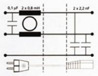
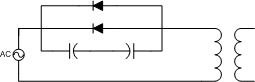
The usual way is to place a X2 rated cap in parallel with the
AC lines. BUT, that doesn't really kill the DC residual on the AC line though! See pic for the usual way to do it. The trafo on the pic still suffers from a mechanical noise. The red component in the middle at the rear is a X2 rated Wima MKP, 0,1uF.
What we need is an easy to implement solution that takes care of the DC. Hopefully some of you guys can come with right one
for this problem. Perhaps, what is really needed is something like this?http://www.lcaudio.dk/index.php?page=12
Go down to "DC filter stop brummet" There you see a schematic.
Couldn't find the filter on the page in english, sorry.
Steen.
Attachments
steenoe said:
A question: Won't that limit the current draw capability, in case
this is implemented in a poweramp?
Steen.
Well, that depends on the size (in µF) of the capacitors. There won't be much voltage across it, so you can have rather large caps. As an example, 10 amps at 230 volts represents an impedance of 23 ohms. If you want the caps to have little impact, let's say you want 0.23 ohms impedance. That means the capacitors need to result in 14000µF, or 28000 if you have two in series. That's a lot, but you'll only need 16V types (albeit large ripple current types.)
Scale according to power requirements, mains frequency and voltage.
Rune
I am sorry, but do not exaktly understand!Well, that depends on the size (in µF) of the capacitors. There won't be much voltage across it, so you can have rather large caps. As an example, 10 amps at 230 volts represents an impedance of 23 ohms. If you want the caps to have little impact, let's say you want 0.23 ohms impedance. That means the capacitors need to result in 14000µF, or 28000 if you have two in series. That's a lot, but you'll only need 16V types (albeit large ripple current types.)
Please clarify if you can! Are you talking about the X2 caps?
That would be an impossible value
 Normally rated about 0,1uF????? Or are you referring to the LC schematic?
I still feel that this would be a great thing for DIY'ers to solve??
Steen.
runebivrin said:That's a lot, but you'll only need 16V types (albeit large ripple current types.)
That's unsafe practice. Everything on the mains side must be specifically mains rated and identified as such.
steenoe said:
I am sorry, but do not exaktly understand!
Please clarify if you can! Are you talking about the X2 caps?
That would be an impossible value
I still feel that this would be a great thing for DIY'ers to solve??
Steen.
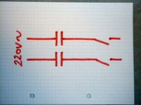
By placing capacitors in series with the transformer primary, you'll prevent any DC component from entering it. It's not about having a capacitor parallel with the transformer. See attached pic.
leadbelly said:
That's unsafe practice. Everything on the mains side must be specifically mains rated and identified as such.
I can't comment on the legal issues, but from a technical standpoint that's ludicrous. I know for a fact that none of the light blubs in my christmas tree lights are rated at 230 volts.
See this for an example: URL=http://www.soundlabsgroup.com.au/lcaudio/lc_audio_mains_dcfilter.htm]LC Audio DC filter[/URL]
Rune
Attachments
runebivrin said:I can't comment on the legal issues, but from a technical standpoint that's ludicrous. I know for a fact that none of the light blubs in my christmas tree lights are rated at 230 volts.
Apples and oranges. (1) Your Christmas tree lights have been IEC stamped somehow or you could not have bought them, so the assembly has been certified as a whole. Similarly that LC Labs product has likely gone through some process. (2) I never said that just putting a capacitor rated at 230V was what was required or even sufficient. The capacitor must be mains certified and labelled as such specifically. It must say something like 180VAC or 250VAC. Look in your electronics catalog for examples.
Maybe that cap was installed in parallel with the power switch. I think that it helps to prevent great inrush current, giving the switch a longer life...but a cassete recorder has no great power consumption. Well...don't know :S
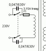
(I took the drawing from a schematic from triodedick) www.triodedick.com
(I took the drawing from a schematic from triodedick) www.triodedick.com
Attachments
leadbelly said:
Apples and oranges. (1) Your Christmas tree lights have been IEC stamped somehow or you could not have bought them, so the assembly has been certified as a whole. Similarly that LC Labs product has likely gone through some process. (2) I never said that just putting a capacitor rated at 230V was what was required or even sufficient. The capacitor must be mains certified and labelled as such specifically. It must say something like 180VAC or 250VAC. Look in your electronics catalog for examples.
And I said "I can't comment on the legal issues", but nevertheless, there is no indication in LC Audio's product that the cap is anything but a bog standard electrolythic capacitor at 22000µF/25V. It may be approved by some authority, but it doesn't say.
It's particularly interesting that the cap will be reverse polarized, albeit at a low voltage.
Are you suggesting that every component in a comupter power supply - which switches the rectified mains voltage - are somehow "mains rated"? Every single resistor?
The bulbs in my christmas light are not specifically certified for use in mains powered equipment, but I will grant you that the sockets most likely are, since they will have 230VAC across the contacts with a broken bulb.
Rune
ErikdeBest said:Maybe that cap was installed in parallel with the power switch. I think that it helps to prevent great inrush current, giving the switch a longer life...but a cassete recorder has no great power consumption. Well...don't know :S
(I took the drawing from a schematic from triodedick) www.triodedick.com
That cap is useful, but not for inrush current, but for preventing voltage spikes on switch-off creating sparks that would shorten the life of the contact surfaces.
Different caps for different purposes!
Rune
- Status
- This old topic is closed. If you want to reopen this topic, contact a moderator using the "Report Post" button.
- Home
- Amplifiers
- Chip Amps
- Cap or caps on ac inlet ?