How good is Hornresp?
So first off- I am aware that this software is free. So even if it's just a bit of fun I am definitely not complaining.
Also, I'm aware that this has probably been discussed a lot before, but cannot find any dedicated thread, other than David's pinned thread. If there is such a thread, please point me in the direction and I will duly delete this thread.
I'm working on tapped horns. My current attitude to using it is based on hoping that it 'probably gives a good general indication' of how a real built horn will sound. And I'm expecting to make at least a couple of mocks in MDF before making my final 'product'.
Is this a reasonable approach?
Are there any known ways in which the software (as excellent as I presume it is) cannot be expected to predict reality?
If you read through the hornresp thread you will see examples of exact match between simulation and measurements. The problem is not the simulation software (it is very precise), the problem is rather how to model the loudspeaker exactly. Precise model will give precise results.
You can definitely expect "a good general indication" from Hornresp.
Most deviations from the simulation to the measured can be accounted for by differences between "as built" and "as simulated"- folds are not the quite same volume or length as a straight expansion, high aspect ratio rectangular shapes are not the same as a circle, exit and entrance shapes are assumed to be circular, "half space" requires one to bury the cabinet in the ground.
In addition, speaker compliance (and reduced Bl) usually progressively limits excursion past Xmax, while Hornresp (and most simulations) don't (can't) factor that in, though up to Xmax predictions should be close to measured.
Voice coil inductance can be variable, double-click on the value for Le to bring up a separate dialog box to enter the semi-inductance parameters.
The Subwoofer DIY Page - Semi-Inductance
Semi-Le_Calc: Calculator for Advanced Inductance Model Incorporating Semi-Inductance
At any rate, there are a lot of things to consider when making new designs, or even changing drivers in an old design.
You can definitely expect "a good general indication" from Hornresp.
Most deviations from the simulation to the measured can be accounted for by differences between "as built" and "as simulated"- folds are not the quite same volume or length as a straight expansion, high aspect ratio rectangular shapes are not the same as a circle, exit and entrance shapes are assumed to be circular, "half space" requires one to bury the cabinet in the ground.
In addition, speaker compliance (and reduced Bl) usually progressively limits excursion past Xmax, while Hornresp (and most simulations) don't (can't) factor that in, though up to Xmax predictions should be close to measured.
Voice coil inductance can be variable, double-click on the value for Le to bring up a separate dialog box to enter the semi-inductance parameters.
The Subwoofer DIY Page - Semi-Inductance
Semi-Le_Calc: Calculator for Advanced Inductance Model Incorporating Semi-Inductance
At any rate, there are a lot of things to consider when making new designs, or even changing drivers in an old design.
Right.
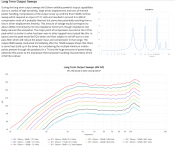
I'm using the maximum SPL feature a lot- and my design does rely on Hornresp's predictions of how the sound changes at different levels of input power.
In fact, with this design, it looks like it's quite easy to have too much headroom. It only sounds the way I intend it to between 200 and 700W. Given it is intended for a live sound reinforcement purpose, I expect I will use a good deal of the wattage.
The "maximum SPL" feature is not indicative of "sound changes" at different levels of input power.
Start thinking in terms of voltage, not watts- and yes, you will want to use all the peak voltage available for live sound reinforcement.
Design so driver excursion in the pass band does not exceed Xmax at Pe, and you will be in the ballpark.
That said, a driver's AES Pe rating (in watts) is measured in free air at the voltage equivalent to driving it's nominal impedance to that level, but it's free air impedance will be far higher than in a TH.
For live use, long term "RMS" limiting with a time constant of longer than 500 ms (milliseconds) should generally be no more than half the AES ratings.
Last edited:
Are there any known ways in which the software (as excellent as I presume it is) cannot be expected to predict reality?
Hornresp does not include the effect of box losses in the TH model. As a result the actual response might look a bit "smoothed" compared to what the sim suggests it should be. You can however emulate the effect of box losses by adding a low value (1) for stuffing in each element of the sim.
Also, when the dimensions of the speaker's box come within a 1/4 wavelength of the frequencies that the speaker is trying to reproduce, there's going to be deviation from the sim, but that's true for most design programs.
Hornresp is a great tool, but it can be a bit difficult to get into it at the first. Once you learn how to use it though, you'll realize how powerful it really is. For example, do you want to model how the position of the driver and/or the position of the vent can impact the response of a vented box? Hornresp can do that...
I think the challenge using Hornresp, is that you need a good accurate way to draw the design, as you are doing iterations in Hornresp. As mentioned, it is the interpretation / translation of the design between Hornresp and the drawing - in both directions.
I am fairly new to Hornresp, and there is a steep initial learning curve. It is deep, and complex - and it usually can do everything; and its just a matter of finding how to do it. I used it for two mass loaded transmission line designs, and it is remarkably precise and accurate, in my experience.
I am fairly new to Hornresp, and there is a steep initial learning curve. It is deep, and complex - and it usually can do everything; and its just a matter of finding how to do it. I used it for two mass loaded transmission line designs, and it is remarkably precise and accurate, in my experience.
The "maximum SPL" feature is not indicative of "sound changes" at different levels of input power.
Start thinking in terms of voltage, not watts- and yes, you will want to use all the peak voltage available for live sound reinforcement.
Design so driver excursion in the pass band does not exceed Xmax at Pe, and you will be in the ballpark.
That said, a driver's AES Pe rating (in watts) is measured in free air at the voltage equivalent to driving it's nominal impedance to that level, but it's free air impedance will be far higher than in a TH.
For live use, long term "RMS" limiting with a time constant of longer than 500 ms (milliseconds) should generally be no more than half the AES ratings.
Ah - I’m confused in that case.
Because the shape of the response in the acoustic power window does change when you adjust the max wattage and displacement parameters. And you can work this feature with only those two options engaged.
What is actually happening then?
Ah yes that’s what I was thinking.
So I’m guessing hornresp assumes an infinitely hard and stiff pathway, with no crosstalk between the neighbouring folds?
And plywood will tend to absorb certain frequencies, as if said infinitely stiff pathway already had some absorbent material applied.
So I’m guessing hornresp assumes an infinitely hard and stiff pathway, with no crosstalk between the neighbouring folds?
And plywood will tend to absorb certain frequencies, as if said infinitely stiff pathway already had some absorbent material applied.
Hornresp does not include the effect of box losses in the TH model. As a result the actual response might look a bit "smoothed" compared to what the sim suggests it should be. You can however emulate the effect of box losses by adding a low value (1) for stuffing in each element of the sim.
Also, when the dimensions of the speaker's box come within a 1/4 wavelength of the frequencies that the speaker is trying to reproduce, there's going to be deviation from the sim, but that's true for most design programs.
Hornresp is a great tool, but it can be a bit difficult to get into it at the first. Once you learn how to use it though, you'll realize how powerful it really is. For example, do you want to model how the position of the driver and/or the position of the vent can impact the response of a vented box? Hornresp can do that...
Ok given the issue with the 1/4WL dimensions, does this mean hornresp will make it appear that a ‘too small’ horn (vs 1/4WL) performs better than it actually will in reality?
I would have thought this is one of the most important things the software is supposed to be telling you?
I would have thought this is one of the most important things the software is supposed to be telling you?
Hornresp does not include the effect of box losses in the TH model. As a result the actual response might look a bit "smoothed" compared to what the sim suggests it should be. You can however emulate the effect of box losses by adding a low value (1) for stuffing in each element of the sim.
Also, when the dimensions of the speaker's box come within a 1/4 wavelength of the frequencies that the speaker is trying to reproduce, there's going to be deviation from the sim, but that's true for most design programs.
Hornresp is a great tool, but it can be a bit difficult to get into it at the first. Once you learn how to use it though, you'll realize how powerful it really is. For example, do you want to model how the position of the driver and/or the position of the vent can impact the response of a vented box? Hornresp can do that...
The "maximum SPL" feature simply is giving an idea of whether the response is reaching the power or displacement limit you have set by frequency.Because the shape of the response in the acoustic power window does change when you adjust the max wattage and displacement parameters. And you can work this feature with only those two options engaged.
What is actually happening then?
In real life, the shape of the response won't respond like that.
Josh Ricci has been kind enough to provide insight as to how response changes when pushed with voltage levels that exceed "normal" operating levels for a wide variety of low frequency enclosures:
Data-Bass: Subwoofer Measurements
You could use the Hornresp inputs provided in his thread:
The Othorn tapped horn
and compare them to the actual measured response on his site to see the differences.
Attached is the Othorn response from 2 volts (4 "watts" @ 4 ohms) to 121 volts (3660 watts @ 4 Ohms) measured at 2 meters, ground plane.
Art
Attachments
Last edited:
Hornresp is a very good representation of lumped-element or one-parameter models. It uses an isophase wavefront based on a series or transmission line of conical elements (if I am understanding the algorithm correctly).
There are, however, limits to these types of models. They primarily fall under a few categories - directivity/diffraction/diffusion, only modeling linear behaviours without losses, and the radiation impedance conditions used for the calculations. The use of an axisymmetric representation also doesn’t always represent what people build, rather than flaws in the modelling technique.
In short, it’s amazing to have this available, let alone for free. However, there are things that require more advanced (and expensive) modelling methods, each of which brings their own problems and quirks. A large portion of the issues with the numerical models like FEA and BEM is that it appears you can drop a CAD file in, mark a few parameters and get trustworthy results, but that is often far from the case.
I think most people designing DIY bass horns (or ported / bandpass enclosures) are very well served by a Hornresp model, a CAD-based layout of the derived parameters using the advanced centre-line method, and some real world measurements of the as-built device - plus some books on acoustic theory.
It might also be useful to get the free version of VACS, if it has the Dyn-Driver tool available; the curve-fitting method to a measured complex electrical impedance of the intended driver may provide a more accurate model than the manufacturer Thiele-Small parameters in whatever Lumped Element tool you use.
How else do you know you're getting it from an enthusiast dedicated to the subjectthis software is free. So even if it's just a bit of fun
")
Here's the link - Hornresp
Not directly related in no way obvious nor would this make any sense unless you actually investigate it to see but you can place a circle into a simulation divided up into 12 parts in horn response and then add one more part so there’s 13.
Sounds weird, doesn’t make sense and it won’t. But deeper in the math that represents in things that are obvious on the surface and that gets results in generic things regardless as mentioned already there’s another layer in another message and another thing to observe and possibly much more important to know .
With a lot of hesitation and awkward nervousness I don’t really want to say something because it never sounds very acceptable or appropriate but I stand in front of my mother if she were alive and show her a picture of the solar system it wouldn’t be a photograph and it wouldn’t be a drawing of planets or anything like thatIt would be a simulation in horn response using nothing more than a number is derived from room in the center of the great pyramid of Giza. Those dimensions which I found on the Internet of all places and all they do is describe a perfect rectangle as a cube in the broader spectrum it’s to the one of a cube that would be 1 to 1 on all sides.
What does numbers are in the hypotenuse of that room and in the metric equivalent or the standard units equivalent or better degrees around perfect circle most of what you’re probably familiar with as in 180 is pi or 3.142857142857 also 22÷7.. Regardless those then create numbers which you can find are 30° as 05238095238… 300 or 30 or three I was there all versions of the speed of light slightly abbreviated and to be like takes 1000 seconds to get to earth so if we’re all concerned with one second we can obviously abbreviate the speed of light to 2.99792458 etc. etc. to make a long story short speed of light divided into four parts is 75 7.5 .. I see that as decimal points and is 749 etc. etc.
Irregardless if you put those numbers in as 30 x 12 ((and a 13th) Mind the zodiac, and it’s error associated with things like the expanding universe would exaggerate if you could tell or see that or understand.. ) times in our response in a compound word you get the most ridiculously accurate portrayal of the solar system in the location of planets in more than one term describes it then you could get anywhere‘s else except a site sponsored by the United States Navy global positioning satellite or NASA in any realistic with decimal points -astronomy site- that real w the numbers were used to define things to find with a telescope
That’s not because of horn response. But if you can find anywhere else where you could put the speed of light into 12 things or 13 and come up with that as the answer well I don’t know where that is or where you would? Except for the fact that they had no choice the number of seconds on earth are the diameter of the sun and the h
Long leg of the right triangle that is the distance to earth, has two other legs at that angle 29.9792458 so the diamond is on in the diameter of the sun squared.
The speed of light squared is the radius of the sun do you order the radius of Jupiter is offset by the same amount as the 5.238095238 in 365.238 days around 360° circles that’s 1462 or so and that number I wanna response will present you all day every day if you give it exactly what I said.
The accuracy of that and what’s required to do that and to come out with that exact number makes no sense none whatsoever consider where the plants are and how much they move around in the orbit where the orbital mean is with a minimum to maximum but what and why that one number would stick out and only because if it’s leap year in four years 365.238 as up to the number that horror response kids us for phase angle of 1440 which is the frequency of 144 which is also what’s you find at 860 Hz which quite possibly makes complete sense when the speed of sound is adjusted to 340 some m/s. Because at 300 or at 360 the numbers that My response give you would be if you do the math the exact same numbers as the quarters of those speed of light at 300 and the circle at 360 when those are the speed of sound 25 50 75 and 100. 3060 90 120. Sounds trivial, Don’t forget CSA don’t forget the TS parameters don’t forget the details that must be included in order for her to respond to come up with what it does and don’t forget multiple drivers don’t forget the parameters which the drivers must stay within her to even do any of that it was creating that he’s going to be in a very narrow range of acceptable things in order for it to do that..
There is a gigantic difference between putting a bunch of numbers into her response and then going to the wizard and sliding the sliders around until you get a response that looks cute and then you build a speaker because it all works just fine over and over again they make some of the stuff that could never ever be you ever built previously without it. But there’s another part about her response in this part doesn’t seem to be used and that is how horn response when given sick information that’s relevant to something very real and very exact it then responds in a way , That only Stephen Hawking can explain and he’s not with us anymore.
It might as the horn response is something that get in the ballpark or you know it provides a good indication of things that are possible but that you can’t quite describe to it so it is what it is close?? I beg to differ there’s boundaries in response to protect you from over telling you things things that aren’t necessary or helpful things that you like to know not to do but there’s no way to know that there could be better so you put a bunch of random numbers and whatever looks best that’s what you build and it works pretty good but there was something better I just needed to resemble The six or 12 parts in a circle can be broken into whatever that is and it goes all the way to 48 or 96 or 192 or 384 I don’t know but somewhere in HR , there is definitely something looking at six or 12 or 72 etc. etc. 24 48?? Because that’s what I would need to look at is further along in this toll thing that’s what you get in the end pieces of that that make a never ending cycle on 860 all the way to infinity.
it is not necessarily just for making speakers it might be that it makes speakers that can fall into the reality of physics in all of the most unique places in the most powerful statements that those would make if we looked.
If you don’t think a para flex or ROAR are particularly accurate or can be high-fi? whatever that means?? Or they have issues somehow a group delay or things ? You should see what they do when they’re based on the speed of light or the arc second of 1000 seconds which was the speed of light in distance a centimeter 30 cm instead of 300,000,000 km put it into her response 12 times and then the 13th for the exit and L4 five. It is not only that there’s more method to the madness in offset driver transmission line. The speed of light twice As radians in 300 cm . Put that in there and see what happens and then decide what our Y or response is accurate he’s a real tests tests that somebody is trying to get an outcome by describing something that is far too hard to describe fairly go to the fair no better place than the perfect circle that mathematically is connected to the perfect rectangle that is the speed of light in the math and it’s all based on what number apparently somehow or response knows that number and that number carries out to 8 decimal points, Before it even shows it’s repetitive nature.
Got to give credit where credit is due. Response makes Bodes Law look dated , and that’s the quarter wave pipe function which found Uranus Pluto series as your own and just about everything since the mid-1800s. You can put that information in response but here’s something more interesting you can change our solar system and impose a change like what happened when the dinosaurs went extinct and what caused that you can produce something just like that because of what is in horn response to represent. It’s crazy so is physics in the solar system and all those numbers. But it starts making so much more sense thanks to horn response.
Last edited:
Hornresp is a very good representation of lumped-element or one-parameter models. It uses an isophase wavefront based on a series or transmission line of conical elements (if I am understanding the algorithm correctly).
There are, however, limits to these types of models. They primarily fall under a few categories - directivity/diffraction/diffusion, only modeling linear behaviours without losses, and the radiation impedance conditions used for the calculations. The use of an axisymmetric representation also doesn’t always represent what people build, rather than flaws in the modelling technique.
In short, it’s amazing to have this available, let alone for free. However, there are things that require more advanced (and expensive) modelling methods, each of which brings their own problems and quirks. A large portion of the issues with the numerical models like FEA and BEM is that it appears you can drop a CAD file in, mark a few parameters and get trustworthy results, but that is often far from the case.
I think most people designing DIY bass horns (or ported / bandpass enclosures) are very well served by a Hornresp model, a CAD-based layout of the derived parameters using the advanced centre-line method, and some real world measurements of the as-built device - plus some books on acoustic theory.
It might also be useful to get the free version of VACS, if it has the Dyn-Driver tool available; the curve-fitting method to a measured complex electrical impedance of the intended driver may provide a more accurate model than the manufacturer Thiele-Small parameters in whatever Lumped Element tool you use.
?? Maybe but , Here’s a thing as well ��?? (I mean in regards to the more expensive in more detail programs ) it might not be appropriate unless I said that but I’m describing is just trying to point out things in physics or rabbit holes that aren’t gonna be helpful and limitations to what you would want to know to describe or to build . I’m not sure if I can explain that right , but hopefully it comes across in the right ways make sense so in advance (sorry )If it kind of doesn’t sound right or to the contrary of what you’re saying as it’s not meant To.
well horn response may not Allow us to tell it enough things that might be necessary to describe something someone wants to build and those details. It may be that it’s those very things that are excessive and that a person shouldn’t be building in order to the achief whatever might be more appropriate and whatever that is or how that would be described without being negative or saying something is better or worse … it is however structured in a way that odd as it may sound limits a person from getting out of hand and becoming stupid silly or just ocd on and chasing things that simply are of no advantage or wouldn’t help anyhow and while that might make and force you to simplify what you’re doing that may be protecting a great many people fromA lot of things that otherwise we would all go crazy on the nooks and crannies and details but it certainly can be found in more expensive programs however those things are made for analyzing much more things that aren’t necessarily speaker industrial applications for noise control and absorption in industrial OSHA regulations etc. etc. noise cancellation or this and that the things that need to be so specific and weird and engineer in ways that the only thing that would happen there’s somebody over engineering a speaker if that’s OK to say without saying we had to ‘dumb’ down everything to a certain level ? because that’s not That’s not fair and certainly not appropriate to tell someone that they have to do their creative idea and limited to any degree however there are things that you can’t really describe and there may be a reason for that not even intentionally by one response but by physics and where that would put things in a matter what if one was aiming for ideal and hopefully that makes sense and sounds fair?
Off the record or just put something out there advance ctr line method,May just be the only way to describe something that’s already wrong to begin with and I only mean that in a way that has to do with pipes and harmonics and results because of them. Because if you’re working that part of the whole fun that we get to have thanks to that little area physics that’s not a part of horns and not a part of bass reflex in a way that’s obvious but quickly becomes obvious pipe if you’re talking to her response about pipe there’s an amazing crazy stuff that happens and it certainly not a way you can see or describe it with a taper shaped or a flate rate or ride or anything like that? It’s the parallel walls is the driver position it’s the distance between the two that’s going to make or break everythingAnd they were centerline abd turns is not helping , in fact it’s doing something wrong in that regards and it has it’s something you can’t see or say where your folding but if you fold and you compound the reason that you’re falling into a compounded situation in the math and physics in the design certainly did miss online is irrelevant it’s those two walls and every single segment that matter??And they were selling his name is not helping in fact it’s doing something wrong in that regards and it has it’s something you can’t tell her her spot where your folding but if you fold and you compound the reason that you’re falling into a compounded situation in the math and physics in the design certainly did miss online is irrelevant it’s those two walls and every single segment that matter . No that’s not necessarily a fact or words seem to be one unless one really dug deeper into what’s really going on in that specific area..
Pipe segments pipe parts that drop right on each other and from both sides as three and one of the exact same length. No turn the switch back with the hole in the floor or the side of the wall that the test is there and the sound does whatever the heck it’s going to do with the parallel walls are maintained and that’s what she described her response that’s what should be happening instead of mixed it into the middle of a turn in this regard. No turn the switch back with the hole in the floor or the side of the wall that the test is there and the sound does whatever the heck it’s going to do with the parallel walls are maintained and that’s what she described her response that’s what should be happening instead of mixed it into the middle of a turn in this regard. Obviously not what do you want to be doing when you’re doing your tab torn in and tapered transmission lines that are folded wherever it’s all screwed up the matter what but this is all part of that unfolding in which created and that set ally method is still erroneous from the get-go because it’s what we have to use but I think that somethings have been overlooked and those things are those parallel walls that the sale was going to be actually hit and be reflected and super imposed upon or low pass filter and if it’s big enough or large enough that it’s gonna go through no matter what to the next of the next set of parallel world and if those are all in sink and in sequence and space as they would be if they were twins Donely that then you’ve got a harmonica playing into the harmonica the other side no matter what somethings working here quickly and if the drivers are sick in those first two parts in the same sequence or in sync with that it would seem they sitting on a gold mine and then when you look at that in other ways to work that represents yes it certainly is as if all along we were missing something I don’t know why?
Last edited:
Can I ask-
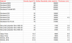
I'm trying to figure out how much stuffing is being applied in the simulation?
At the moment I have it on '2200'. There are no units as far as I can see.
In particular, is this an acheivable level of stuffing in the real world?
Weight is shown for densities < 1000, the rest you will have to calculate. Here's a re-post of reference values David posted in his thread:
Attachments
Thanks for that... Detailed reply.
Though the somewhat erratic syntax and odd choice of narrative makes things difficult to follow at times.
I'm also unsure if it is a response specific to this thread.
Though the somewhat erratic syntax and odd choice of narrative makes things difficult to follow at times.
I'm also unsure if it is a response specific to this thread.
?? Maybe
Last edited by a moderator:
How else do you know you're getting it from an enthusiast dedicated to the subject
Here's the link - Hornresp
I've been working on models for about three months now. Just in order to make my final draft, I wanted to get a number of opinions on it before I spend £190 on my driver.
- Home
- Loudspeakers
- Subwoofers
- How good is Hornresp?