This is a new thread to detail the building of the UNSET Beta Board, and its use in building an UNSET amp. This thread should only be used for discussing the board build, and all other UNSET questions and discussion should go into the existing UNSET thread here:
UNSET is coming?
These first few posts will contain the build documentation as it exists today. It will continuously be updated with the latest build documents. Some of these are a bit thin on info, but I need to put it up so that some can start their builds. So far only 8 people have boards. I'm sure that new issues will arise, and they will be addressed here.
There are two schematics. The Eagle schematic was used to generate the board files. It is somewhat confusing with two sets of mosfets and all the jumper pads, but it is an exact match for the board.
The Simplified schematic has all the unnecessary stuff removed, thus it is a bit easier to follow.
The preliminary Bill Of Material (BOM) is here. All of the part listed are the same as what's in my board which has been tested to 660 volts.
I have added an Excel version of the BOM. I had to zip it so it would upload since .xls is not supported.
Attachments
Last edited:
Very exciting! Thank you. Thank you for your hard work and sharing it with us.
I will be traveling for the next 3 weeks, but will get back prepared and ready to build a 6DQ5 UNSET using the v2.2 Beta board.
Reading the material you provided above more carefully later will probably provoke more questions, but for now I have two:
1. It is not clear to me how to use your “OctaloutputMatrix” wrt the physical PCB. It would be very helpful if you could snap a picture or two of your populated PCB to show and explain how you wired the output tubes to the board.
2. The BOM above lists IXTP15N50L2 for Q1. Previously you mentioned in post #264 that you used IXTP3N100D2 successfully for Q1 in your development work.
https://www.diyaudio.com/forums/tubelab/340856-unset-coming-27.html#post6724450
May I assume IXTP3N100D2 is still acceptable? I bought several of them a couple of weeks ago.
This is a new thread to detail the building of the UNSET Beta Board, and its use in building an UNSET amp. This thread should only be used for discussing the board build, and all other UNSET questions and discussion should go into the existing UNSET thread here:
UNSET is coming?
These first few posts will contain the build documentation as it exists today. It will continuously be updated with the latest build documents. Some of these are a bit thin on info, but I need to put it up so that some can start their builds. So far only 8 people have boards. I'm sure that new issues will arise, and they will be addressed here.
There are two schematics. The Eagle schematic was used to generate the board files. It is somewhat confusing with two sets of mosfets and all the jumper pads, but it is an exact match for the board.
The Simplified schematic has all the unnecessary stuff removed, thus it is a bit easier to follow.
The preliminary Bill Of Material (BOM) is here. All of the part listed are the same as what's in my board which has been tested to 660 volts.
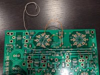
.......it has begun !

Here is my take on using the matrix to wire the socket for a 6DQ5. The wires are just being used for indicators right now. Did I get this right?...
1. It is not clear to me how to use your “OctaloutputMatrix” wrt the physical PCB. It would be very helpful if you could snap a picture or two of your populated PCB to show and explain how you wired the output tubes to the board.
...
Attachments
Yes, that's right, and probably the best way to wire it if 6DQ5's and the rare 8236 are the only tubes that you will ever use.
If you leave out the redundant connections and wire only pin 3 to the cathode buss, pin 5 to the control grid buss, and pin 8 to the screen grid buss, then you can use the 6DQ5, 6CB5, 6CL5, 6CD6, 6DN6, 6EX6, 6GC6, and 8068, pretty much interchangeably just by adjusting the bias. The 6BG6 is also pin compatible with this setup, but being a 6L6GB in disguise, it needs a lot more screen voltage.
I plan to rewire my board for these tubes tonight since I have a bunch of several of them.
Keep the wires to as short as possible to avoid unnecessary coupling. Sweep tubes also work quite well in RF amps and make good power oscillators.
Some of these tubes have hungry heaters (6LW6 is 2.65A), so I use a thicker wire for the heater connection. The length is short, so you don't have to go crazy, but wire wrap wire won't work.....yes, I have seen a tube amp that someone built with wire wrap wire with a cigar box for the chassis.....the crazy thing is that it worked, and sounded pretty good.
Here is my take on using the matrix to wire the socket for a 6DQ5. The wires are just being used for indicators right now. Did I get this right?
Is it necessary to “double connect” to G1, G2 and K/G3? Perhaps George could clarify.
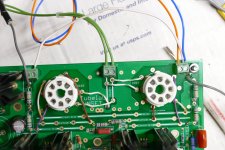
spiggs, check the heater connections - it looks like the heater wires are both connected to 2-1. I believe they should go to “HEATER 2-1, and 2-2 respectively.
Is it necessary to “double connect” to G1, G2 and K/G3? Perhaps George could clarify.
spiggs, check the heater connections - it looks like the heater wires are both connected to 2-1. I believe they should go to “HEATER 2-1, and 2-2 respectively.
The heater connections are both connected to Heater 2-1. One should go to each buss. I missed than when I looked at the picture the first time.
As I stated in post #8 it is not necessary to double connect the cathode or grids, in fact doing so limits the variety of tubes that can be used in the amp without rewiring.
I will get a picture of my board as it is currently wired, for 26LW6 / 26HU5 and again after rewiring for the 6DQ5. I plan to run 6DQ5's, 6CD6's, 6CB5's and 25DN6's as I have over 100 of them that I got for fifty cents each.
If you look at the OctalOutputMatrix picture there are three groups of tubes. Each group can be handled with a common set of connections if you wire the sockets according to the blue row at the top of each group. This carefully picks out the common connections in a group of tubes that each have a slightly different pin out.
Any tube listed to the right of any green row in each group can be used with no wiring changes if the socket is wired according to the connections at the top in blue. So any tube in Group 1 will work in my SSE board. Note that this applies to pin connections only. All of these tubes do not have the same electrical characteristics, IE a 6V6 will work in an SSE board, but at 300 volts, not 450 volts.
The 6 green rows below the three groups list the wiring for a few common tubes that might be useful in the UNSET and the unique socket wiring for them.
Back when I was a kid in the 60's building guitar amps out of parts from dead 1950's TV sets, I found out that a 6BQ6 and a 6DQ6 sweep tube out of a TV would work in a guitar amp wired for a 6V6 or a 6L6 tube if you simply connected a plate cap to pin 3 of the socket. This led me down a 50+ year journey of finding all the tubes that could be swapped around in this manner. It took a lot of work with several tube manuals back in the late 60's and early 70's. It's a lot easier today with a computer.
Last edited:
The first picture is of the matrix as wired for 26LW6 / 26HU5.
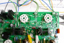
I have added another picture after I wired it for 6DQ5's, 6CD6's, 6CB5's and 25DN6's.
The 25DN6's cranked out an easy 15 watts on 450 volts at 80 ma (1KHz) with the 1500 ohm Toroidys wired for 3000 ohms. The ridiculous saturation seen with high current was not present and 12 watts at 5% THD at 50 Hz was possible on both channels. Saturation was seen above 8 watts at 20 Hz. This is similar to the Transcendars which make less power (12 watts) due to the DCR loss. The26DQ5's that I have are International Servicemaster brand with GT. BRITAIN and 26DQ5 screened on the side. My experience with some similar looking 6KT6's says that these are really Japanese or Korean tubes, and only a small step above junk. The 50 cent 25DN6's easily kick their butt, so after some cooling off time I will connect up a 6.3 volt source and dig out some real 6DQ5's.
Attachments
Last edited:
The first picture is of the matrix as wired for 26LW6 / 26HU5.
I have added another picture after I wired it for 6DQ5's, 6CD6's, 6CB5's and 25DN6's.
The 25DN6's cranked out an easy 15 watts on 450 volts at 80 ma (1KHz) with the 1500 ohm Toroidys wired for 3000 ohms. The ridiculous saturation seen with high current was not present and 12 watts at 5% THD at 50 Hz was possible on both channels. Saturation was seen above 8 watts at 20 Hz. This is similar to the Transcendars which make less power (12 watts) due to the DCR loss. The26DQ5's that I have are International Servicemaster brand with GT. BRITAIN and 26DQ5 screened on the side. My experience with some similar looking 6KT6's says that these are really Japanese or Korean tubes, and only a small step above junk. The 50 cent 25DN6's easily kick their butt, so after some cooling off time I will connect up a 6.3 volt source and dig out some real 6DQ5's.
Awesome stuff George, Thank You. Hoping you or someone put up a pic for the group1 wiring as well. Most of the tubes in groups 2 & 3 are near impossible in my part of the world.
As I stated in post #11 the Toroidys that I have seem to work about as good as similar sized EI OPT's at the typical current that they would be used at for the application they are intended for. They are more efficient than the Transcendar EI transformer, and thus make more power at the same current.
The transformers are specified for a parallel pair of 300B's or a pair of KT88's in SE. Either of these setups should run about 140 to 180 mA and make 20 or so watts. The Toroidys do seem to work at that level. They do not work at the "60 watt nominal" and "300 mA nominal" rating stated right on the transformer.
The proof will be in the listening test which I have not done yet. My board is in the middle of a big science experiment right now.
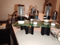
The game is afoot...
The first components are in place.
And of course the one resistor value I don't have is needed now
Oh well.
Tubes on top (just trying some candidates here), components below deck.
George,
C9 is an electrolytic on the board/schematic, but the BoM lists a 100n foil cap.
What value should we put in there?
Attachments
C9 should be the 100nF cap. Choose something sized to fit the board. My original prototype used a 10 or 22 uF electrolytic, but it cause the bias to come up slower than the screen voltage leading to a huge current surge. The board even seems stable without C9, but I think that a bypass here is a good thing.
What resistor are you missing? Some parts are non critical and the value might have been chosen based on what I had when I built the very first board, and I never found a need to change it.
What resistor are you missing? Some parts are non critical and the value might have been chosen based on what I had when I built the very first board, and I never found a need to change it.
- Home
- More Vendors...
- Tubelab
- UNSET Beta Board Build