I've trying to spin up a new amplifier design--at least 200W into 8 ohms.
My simulation experiments have shown me that the output triple is the way to go, as opposed to the various CFP variations. I am using a diamond buffer like Bob Cordell shows on p. 267 of his 2nd edition book. My outputs are NJW0281 and NJW0302, 4 of each in parallel. My drivers are MJE15032 and MJE15033. My pre-drivers are KSC3503 and KSA1381. All of this is pretty much as Bob suggests.
I've been trying to increase the bandwidth of the output stage from the 20 MHz range, but have been frustrated. The MJE1503x parts were limiting things. I tried substituting an NJW0281/0302 for each of them, and that helped a little.
Then I tried a thing. I replaced the MJE1503x with 3 each of the KSC3503 and KSA1381 wired in parallel. This increased the bandwidth of the output stage by about a FACTOR OF 3! I now have 45 degrees of phase shift at 27 MHz and -3 dB at over 60 MHz. You may ask why I need a 60 MHZ output stage. The answer is that I'm wanting to increase the feedback factor at 20 kHz, and the first way of doing that is moving the 2nd pole further out.
Has anyone else used multiple paralleled KSC3503 and KSA1381 as drivers?
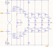
I'm attaching a schematic of the triple output stage.
My simulation experiments have shown me that the output triple is the way to go, as opposed to the various CFP variations. I am using a diamond buffer like Bob Cordell shows on p. 267 of his 2nd edition book. My outputs are NJW0281 and NJW0302, 4 of each in parallel. My drivers are MJE15032 and MJE15033. My pre-drivers are KSC3503 and KSA1381. All of this is pretty much as Bob suggests.
I've been trying to increase the bandwidth of the output stage from the 20 MHz range, but have been frustrated. The MJE1503x parts were limiting things. I tried substituting an NJW0281/0302 for each of them, and that helped a little.
Then I tried a thing. I replaced the MJE1503x with 3 each of the KSC3503 and KSA1381 wired in parallel. This increased the bandwidth of the output stage by about a FACTOR OF 3! I now have 45 degrees of phase shift at 27 MHz and -3 dB at over 60 MHz. You may ask why I need a 60 MHZ output stage. The answer is that I'm wanting to increase the feedback factor at 20 kHz, and the first way of doing that is moving the 2nd pole further out.
Has anyone else used multiple paralleled KSC3503 and KSA1381 as drivers?
I'm attaching a schematic of the triple output stage.
Attachments
Admittedly never did it myself. Might worth trying but I'd perhaps watch out for, a/ the combined safe operating area not to be breached, and b/ good current sharing not to be compromised by current hogging (high value base stopping resistor and lack of degeneration at emitter could encourage current hogging).
Wow, such a useful tread!
Yes, clearly!
Heh, yes, they can!
But are you sure, your new faster EF3 are free from oscillation under load?
Things are usually the same. You simulate and build an amp with EF3. Set bias and all seemed fine. Next you provide test load nd some small-signal test.
All ok and you try to test clip limit. And an amp's PCB are naturally burn.
This is because badly designed EF3 are unstable at any capacitive load, especially with fast last third stage transistors having huge fT/Ic dependance. Usually it oscillates at ~15-22 MHz. Just add some realistic inductances at emitters/bases and you easily see what happens.
Check this behaviour with very simple bench:
https://www.diyaudio.com/forums/solid-state/359253-driving-lateral-mosfets-8.html#post6369321
I've been trying to increase the bandwidth of the output stage from the 20 MHz range, but have been frustrated. The MJE1503x parts were limiting things.
Yes, clearly!
Then I tried a thing. I replaced the MJE1503x with 3 each of the KSC3503 and KSA1381 wired in parallel. This increased the bandwidth of the output stage by about a FACTOR OF 3!
Heh, yes, they can!
But are you sure, your new faster EF3 are free from oscillation under load?
Things are usually the same. You simulate and build an amp with EF3. Set bias and all seemed fine. Next you provide test load nd some small-signal test.
All ok and you try to test clip limit. And an amp's PCB are naturally burn.
This is because badly designed EF3 are unstable at any capacitive load, especially with fast last third stage transistors having huge fT/Ic dependance. Usually it oscillates at ~15-22 MHz. Just add some realistic inductances at emitters/bases and you easily see what happens.
Check this behaviour with very simple bench:
https://www.diyaudio.com/forums/solid-state/359253-driving-lateral-mosfets-8.html#post6369321
Yes, emitter degeneration is a better way to share current, beta varies between devices a lot, so the base resistors are not so good (or are they just stoppers? in which case you might have very poor sharing in that circuit)Admittedly never did it myself. Might worth trying but I'd perhaps watch out for, a/ the combined safe operating area not to be breached, and b/ good current sharing not to be compromised by current hogging (high value base stopping resistor and lack of degeneration at emitter could encourage current hogging).
Although it may not make a difference in practice, it is more customary to have each driver driving its own output, rather than 3 in parallel driving 3 in parallel. You could probably reduce parasitic PCB wiring parasitic that way (less metal to make unwanted capacitances to ground, which eat away at phase margins).
Yes, emitter degeneration is a better way to share current, beta varies between devices a lot, so the base resistors are not so good (or are they just stoppers? in which case you might have very poor sharing in that circuit)
Higher Hfe transistors require less Ib for the same Ie than do the lower Hfe transistors when working paralleled. When using a Rb then higher Hfe transistors would be driven at a slightly higher Vbe than are those of lower Hfe coworkers, due to a slightly lower voltage drop over the Rb, further deepening the unevenness in Ie. Power amp design books usually recommend a 0R22 emitter degeneration for paralleled output transistors, and a resistor no more than 10x that, or 2R2, at the base. So I guess for the paralleled driver stage I would put a 3R3 at the emitter, and 33R at the base, and go from there.
I looked carefully at SOA. That's why there are 3. You're correct that I need to put some resistors on the emitters for current sharing. Thanks for the reminder.Might worth trying but I'd perhaps watch out for, a/ the combined safe operating area not to be breached, and b/ good current sharing not to be compromised by current hogging (high value base stopping resistor and lack of degeneration at emitter could encourage current hogging).
AS long as you dont mind another device on the BOM, perhaps look at KSC2690/KSA1220
That is a heftier device with high fT and low Cob. I'll give it a shot. Are there SPICE models you like to use for that device? I'm wary of factory SPICE models.
Heh, yes, they can!
But are you sure, your new faster EF3 are free from oscillation under load?
Things are usually the same. You simulate and build an amp with EF3. Set bias and all seemed fine. Next you provide test load nd some small-signal test.
All ok and you try to test clip limit. And an amp's PCB are naturally burn.
This is because badly designed EF3 are unstable at any capacitive load, especially with fast last third stage transistors having huge fT/Ic dependance. Usually it oscillates at ~15-22 MHz. Just add some realistic inductances at emitters/bases and you easily see what happens.
Check this behaviour with very simple bench:
https://www.diyaudio.com/forums/solid-state/359253-driving-lateral-mosfets-8.html#post6369321
BesPav, you have some of the best responses. I very much appreciate them. Also, the link is rich with information
Keeping my EF-triple free from oscillation is my highest priority. This is not my first rodeo. In the 1990s, I designed several production amplifiers with EF-triples.
The thing with EF-triples is that as you approach the rails, all of the Cob values increase by nearly an order of magnitude. At the same time, output device fT drops due to high current. I never faced self-destructive oscillation, but the RF fuzz caused lower efficiency and higher THD (and earlier onset of clipping). I fixed it then, and I know I can fix it now, even though these new devices have much higher bandwidth. My simulation models include the pin inductances. Still, I don't really trust the models at these frequencies. The only way I'll know if I have RF oscillation is to build it and drive various reactive loads to full power.
The inherent problem with EF stages is that they don't like to be driven by a source impedance that increases with frequency, while at the same time driving a load impedance that drops with frequency. Unfortunately, EF stages have output impedance that increases with frequency, and input impedance that decreases with frequency. In short, they don't like each other, and if you add a capacitive load to that problem, you're likely in a lot of trouble.
What's interesting here, is that my production amplifiers (for car audio) never had inductors before the speaker terminals. I knew that no one was going to drive a capacitive speaker in a car, so I left that out. For home audio, people do drive capacitive speakers, so the inductor will go in.
Use better/faster driver. My vote is 2SC4883/2SA1859.
Sajti
Thanks for the tip. These have good specs. They seem pretty similar to the Fairchild/ON KSC2690/KSA1220. I see that Keantoken has modeled them here:
Sanken 2SC4883 and 2SA1859 SPICE models with quasi-saturation
I'm definitely going to give them a try.
BesPav, you have some of the best responses. I very much appreciate them. Also, the link is rich with information
Thanks, feel free to ask.
Keeping my EF-triple free from oscillation is my highest priority.
Heh, let's try!
The inherent problem with EF stages is that they don't like to be driven by a source impedance that increases with frequency, while at the same time driving a load impedance that drops with frequency.
Clearly!
I've write about this some time ago.
https://www.diyaudio.com/forums/sol...paralleling-transistors-ok-6.html#post6181849
Also feel free to read YAPamp design notes here:
The YAP Output Stage
This is exact you talked about. Yes, Cob/Vce dependance, Yes, impedance conversion, Yes, fT/Ic dependance and you're as designer must account for all of this.
Designing stable and reliable EF3 are a task themselve.
Choose your way from my post with different approaches and we'll talk about more deeply.
Really you doesn't need much bandwidth from OPS. You need them to have stable by frequency poles. Most of the freq drop in OPS you can compensate with some response rise in the frontend. So really you'll tune overall response curve, not only OPS.
Last edited:
You may ask why I need a 60 MHZ output stage. The answer is that I'm wanting to increase the feedback factor at 20 kHz, and the first way of doing that is moving the 2nd pole further out.
Heh, not only OPS fT allow you to have more feedback...
")
What do you think about 90 dB feedback depth at 20 kHz in amp with 3 MHz UGF?
Opamp + Common base
What do you think about 90 dB feedback depth at 20 kHz in amp with 3 MHz UGF?
I agree with the 1st commenter on the linked thread: "Interesting..."
Thanks, feel free to ask.
Choose your way from my post with different approaches and we'll talk about more deeply.
I read through your links, and you say to choose one of two methods:
1) slow down the middle EF or
2) slow down the final EF so that the middle stage drives the load directly at high frequency.
That sounds right to me. Back in my 1990's designs, I slowed down the middle stage.
Either approach makes the OPS a double-EF as the amp approaches the problematic 10 MHz range, thus making it more stable. Approach 1) makes sense if the driver is already kind of slow, like the MJE1503x. Approach 2) makes sense if I use the appropriate KSA/KSC parts for the drivers. Then the outputs are already the slowest.
Of those 2 approaches, I think capacitor bypassing the final stage at high frequency may make the most sense. It's already the slowest stage, and most prone to fT shifting because of its large current swing. I have no need for high current drive at 10 MHz. There will be some pole-zero phase-shift swapping as the final stage moves out of the way, but it seems manageable.
I read through your links, and you say to choose one of two methods:
1) slow down the middle EF or
2) slow down the final EF so that the middle stage drives the load directly at high frequency.
That sounds right to me. Back in my 1990's designs, I slowed down the middle stage.
Yes, clearly!
Of those 2 approaches, I think capacitor bypassing the final stage at high frequency may make the most sense. It's already the slowest stage, and most prone to fT shifting because of its large current swing. I have no need for high current drive at 10 MHz. There will be some pole-zero phase-shift swapping as the final stage moves out of the way, but it seems manageable.
Also try to use a way slow output devices like MJL21194/MJL21193.
The have huge crystals, wide SOA, an order stable fT/Ic and are enough fast to any of the audio amplifier tasks.
Try simple attached models and compare.
Attachments
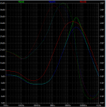
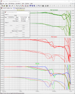
The graphs in simple model shows an output resistance of the overall OPS.
Green curve is a fast OPS without slowdown of the 2nd stage.
Blue curve is a fast OPS with slowdowning 2nd stage
Red curve is an OPS with MJLs.
The sign of instability is a high-Q peak on the green curve. Check phase, the small frequency change ended up in phase turning to reversal. You need to lower such a peak by any methods.
Hi Bespav,
I think I will keep the NJW0281/NJW0302, not for bandwidth but for flat beta vs current. These yield much lower THD than my old triples back in the 1990's.
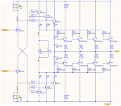
I did an experiment. First, I fixed the ballast resistor problem in my drivers (this did not noticeably affect the AC response) Then I put a Zoebel across the outputs as shown, to bypass them at high frequencies. I tried just C first, but there was too much pole-zero wobble around 5 MHz.
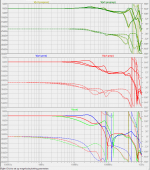
That really cleaned up the AC response. The before and after plots are shown, along with the revised schematic. I think I can safely close a 10 MHz UGF loop around this output stage.
The plots show AC response with output of -58V, 0V, and 58V into 4 ohms. As expected, BW drops heavily at -58 and +58 V on the outputs. My transistor models include 35 nH in series with each base & emitter, and 10 nH in series with each collector.
I think I will keep the NJW0281/NJW0302, not for bandwidth but for flat beta vs current. These yield much lower THD than my old triples back in the 1990's.
I did an experiment. First, I fixed the ballast resistor problem in my drivers (this did not noticeably affect the AC response) Then I put a Zoebel across the outputs as shown, to bypass them at high frequencies. I tried just C first, but there was too much pole-zero wobble around 5 MHz.
That really cleaned up the AC response. The before and after plots are shown, along with the revised schematic. I think I can safely close a 10 MHz UGF loop around this output stage.
The plots show AC response with output of -58V, 0V, and 58V into 4 ohms. As expected, BW drops heavily at -58 and +58 V on the outputs. My transistor models include 35 nH in series with each base & emitter, and 10 nH in series with each collector.
Attachments
- Status
- This old topic is closed. If you want to reopen this topic, contact a moderator using the "Report Post" button.
- Home
- Amplifiers
- Solid State
- Removing MJE1503x in an Output Triple