Hi Guys
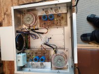
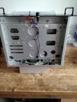
New on here. Just bit of advice as I don't know much about builds of op amps. I got this pair which are in pretty good nick and have used a good old spare chassis I had lying around to mount these in.
Now am I right that the heat sinks don't need earthing. I've earthed the j50 and k135s all powered up okay and I'm getting 47.5v on main rails. Not measured anything else yet just letting them burn in for a bit.
I now need to mount the pots which I think are 47k? And obviously put in the output input XLR sockets in. I have a spare set of old led lights for the on off switch but was wondering if I could run them from the vu meter points +12v put in a shunt resistor to get voltages down. Not sure what rating they are? Need to work that out.
I also have a decent fan but it's 115vac so need to work out how to get that working as I also have a pair of heat sensors you mount onto the heatsinks so think I'mgonna need to build a module to get that working with right voltage rating or just buy a 240v fan. But I'd rather use what I have if possible. So quite a bit to do yet. But I'd like to get it right and not blow it up.
When I got these they where mounted in a homemade chassis but it was a mess and everything in there apart from the modules had all been sprayed black including the wiring. The pots where covered in gather tape and on switch on you could not turn the volume down it was like it was just set at a level. You could increase volume. So is this normal or was it wired up wrong? Again wires connected together using a bit of solder and insulation tape. Hence moved into a decent chassis.
Anyhow any feedback welcome.
Cheers
An audio power amp is not the same thing as an opamp.I don't know much about builds of op amps
Now am I right that the heat sinks don't need earthing. I've earthed the j50 and k135s
Never randomly connect part of a circuit to ground unless you understand the circuit....
Sometimes heatsinks are meant to float, sometimes not.
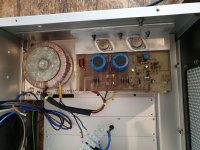
Can you post some pics and some identification of these modules?
Bit odd keep having to have my post looked at by moderators it says before posting? ....
On other forums, spammers and troublemakers can make quite a stink before a moderator can act. It is quite common to limit new members for the first several posts. Has been for years. Just post calmly so you look like a reasonable person, not a spammer or agitator. Yes, several posts because spammers usually do post a blank "Hi there" before dumping a payload.
What Country are you in?I also have a decent fan but it's 115vac
Fill that data in your profile .
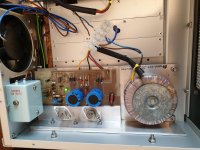
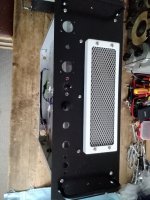
Your picture shows them bolted to chassis so they *are* earthed.Now am I right that the heat sinks don't need earthing.
Series, not shunt.old led lights for the on off switch but was wondering if I could run them from the vu meter points +12v put in a shunt resistor to get voltages down
SCARY mains wiring around that terminal strip in the middle of the picture.
J50 k135
Basically they are both physically isolated from the heat sink so there's no earth connection there. I assumed this was normal method of instalation for these! Then via the screws and Solder tags and wire they are physically grounded to chassis. Now I know one leg is connected to the casing which is also physically earthed. Now I could of just connected them straight to the heatsink with no mica insulation or screw tab insulation. Then they would still be earthed via the heatsink but not physically. So are you saying they don't need an earth contact at all? And should be physically isolated from earth?
I'm assuming these are the power outputs? Not signal outputs?
I think and as mentioned valve gear fine this gear new to me so I'm still figuring out how these circuits work as there are quite a few variations. Plus the low voltage high current another learning curve. I'm used to 450v to 700v plus but these circuits seem to run at about 60v max depending on output and higher amps over the 10 plus mark in some instances. Seems based on getting distortion as low as possible.
Digressed there.
But signal I think is from a 2sa 872 plus it also looks like you have I think it's a darlington configuration for additional gain via pair of 2sa 872 and a pair of bf469 and bf 470.
So will they have a signal was your question? If there just for power output not signal then no there would be no signal. But as you say if there is they will burn out? Which would mean no earth connection at all. Sorry no pictures as its all neatly installed underneath the Ali boards and I'd have to remove everything just to show you and to be honest I can't stand that heatsink grease and having to re do it all no thanks it gets everywhere.
So pull this apart if I'm on the wrong track.
Ah I see what your saying now. So the T03 has to still be isolated from the heatsink but not earthed at all? The only reason I ask is the washers the screws fit through at the base of the T03 cases also stop them from making contact to the heatsink. Or do those need to be removed?
Take note there then hence I fired it up with no load and my dodgy looking mains connection. My rule of thumb do a bit check then double check. Not sure ask. Add a bit check re check then continue on. Not one to just hook it all up in one go and blast 240 volts through only to find as you've just said bang. Or just don't work so then you need to go through everything again or it's mass pay out and all that work down the drain.
Thanks for that much appreciated.
I've got it. From what I remember is the nut had a piece of earth sleeving on it obviously to stop it touching the heatsink then just nut and washer underneath. So nut and washer was touching pcb. I bought a kit which had a washer which slides up the heatsink hole to stop nut touching heatsink but it protrudes underneath so there's no contact to the heatsink or pcb. Hence the earth tab added to earth it. So I'll sleeve the nut and just add the nut and washer to the pcb underneath. There's no type of pad there between nut and pcb it touches the track directly. Didn't give it much thought to be honest like say never touched these before. So don't now what the method of installation is. Just watched a video and general look on web and thats basically how it was attached with the earth tab. So went by that then had a think. Then thought best to get advice to make sure I'm doing this right.
But appreciate your help and patience.
But appreciate your help and patience.
Hi Shockhazard,
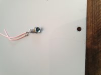
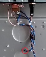
Do hope you're planning a nice little rubber grommet, or one of those segmented nylon thingies for this hole.
Also, if this is the chamber you were talking about 'reducing EMI' -- with 240V line in it, the sensitive, high impedance stuff will still see plenty of EMI from the incoming power.")
Cheers
edit: Ooh, and welcome to the forum!
Do hope you're planning a nice little rubber grommet, or one of those segmented nylon thingies for this hole.
Also, if this is the chamber you were talking about 'reducing EMI' -- with 240V line in it, the sensitive, high impedance stuff will still see plenty of EMI from the incoming power.
Cheers
edit: Ooh, and welcome to the forum!
Attachments
Last edited:
Be very, very careful with those... If you blow them up you'll be in a world of hurt getting replacements.the j50 and k135s
- Home
- Amplifiers
- Solid State
- b k electronics mosfet 100 watt modules