Greetings, Friends. I bought myself a tube amp kit, the DIY 6N1 + 6P3P + 5Z4P 7W model. I found this one on Ali, but it's also on the wiBay for a slightly higher price. I elected to save a few more dollars by getting the kit without tubes, blithely thinking it would be easy enough to sub common tubes, hopefully made by JJ. Easy to get, easier to get better-sounding tubes. Does Ruby do 6N1's?
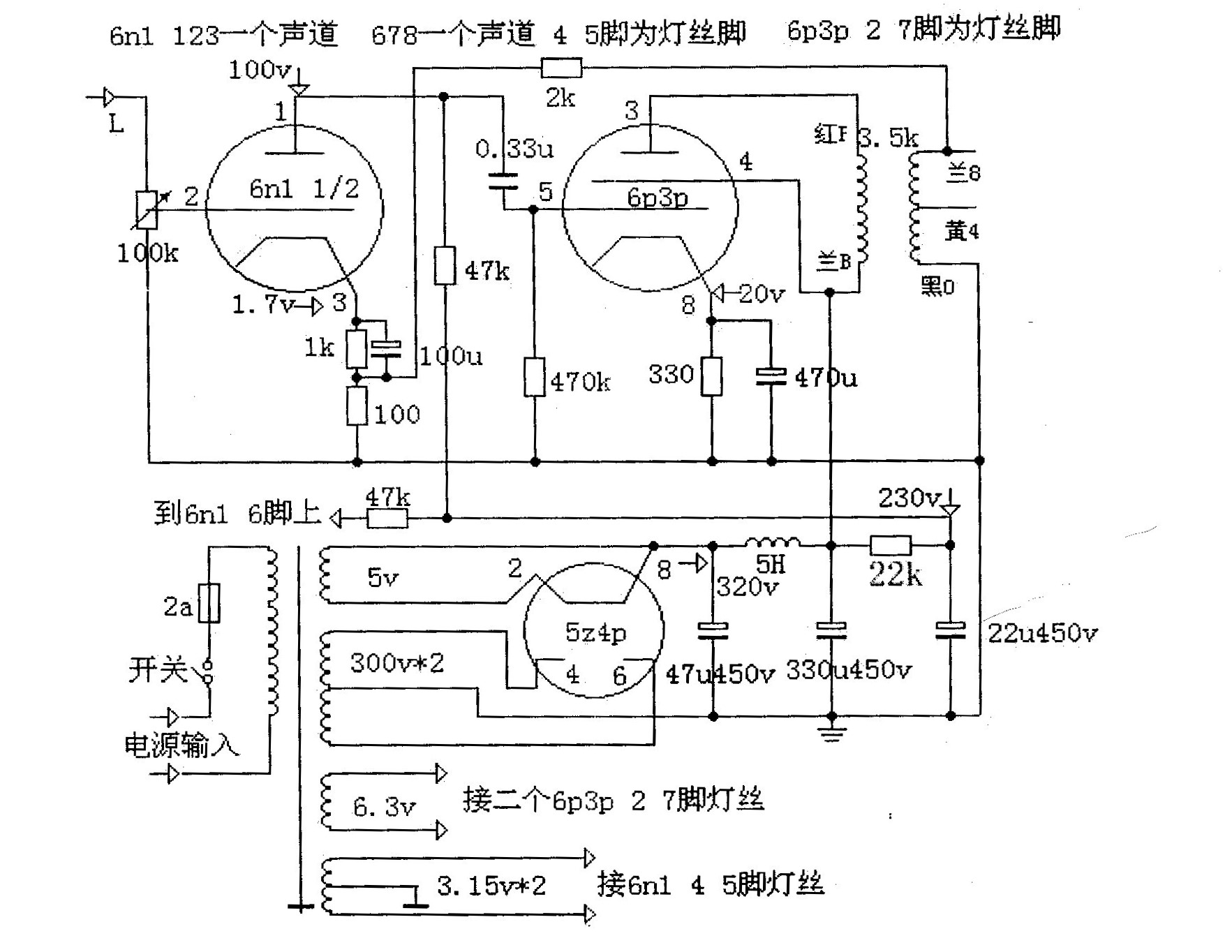
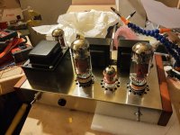
I built the amp as drawn here and put a 5AR4 in the socket, along with a 12AX7 and a pair of 6L6, lookin' good:

hooked up a pair of speakers, turned it on, after 15 seconds a loud, high oscillation started, I saw arcing in the 5AR4, and the fuse went. Tore the whole thing apart, the only mistake I found was never connecting the signal ground to the main ground, and with that fixed I still get arcing in the 5AR4 about 15 seconds after powering on. So I figure that tube's done for.
The included schematic uses very large caps in the CLC circuit with a 5H choke. Most designs I've seen use much smaller caps, less than 20uF, so I think I'll move the 47uF to the 2nd position and put a 15uF in the 1st. I floated a question about this project on another thread and was advised to change the Plate and Cathode resistors for the driver tube to 100K and 1.2K, respectively. So I've made those changes to the drawing and translated what needed it.
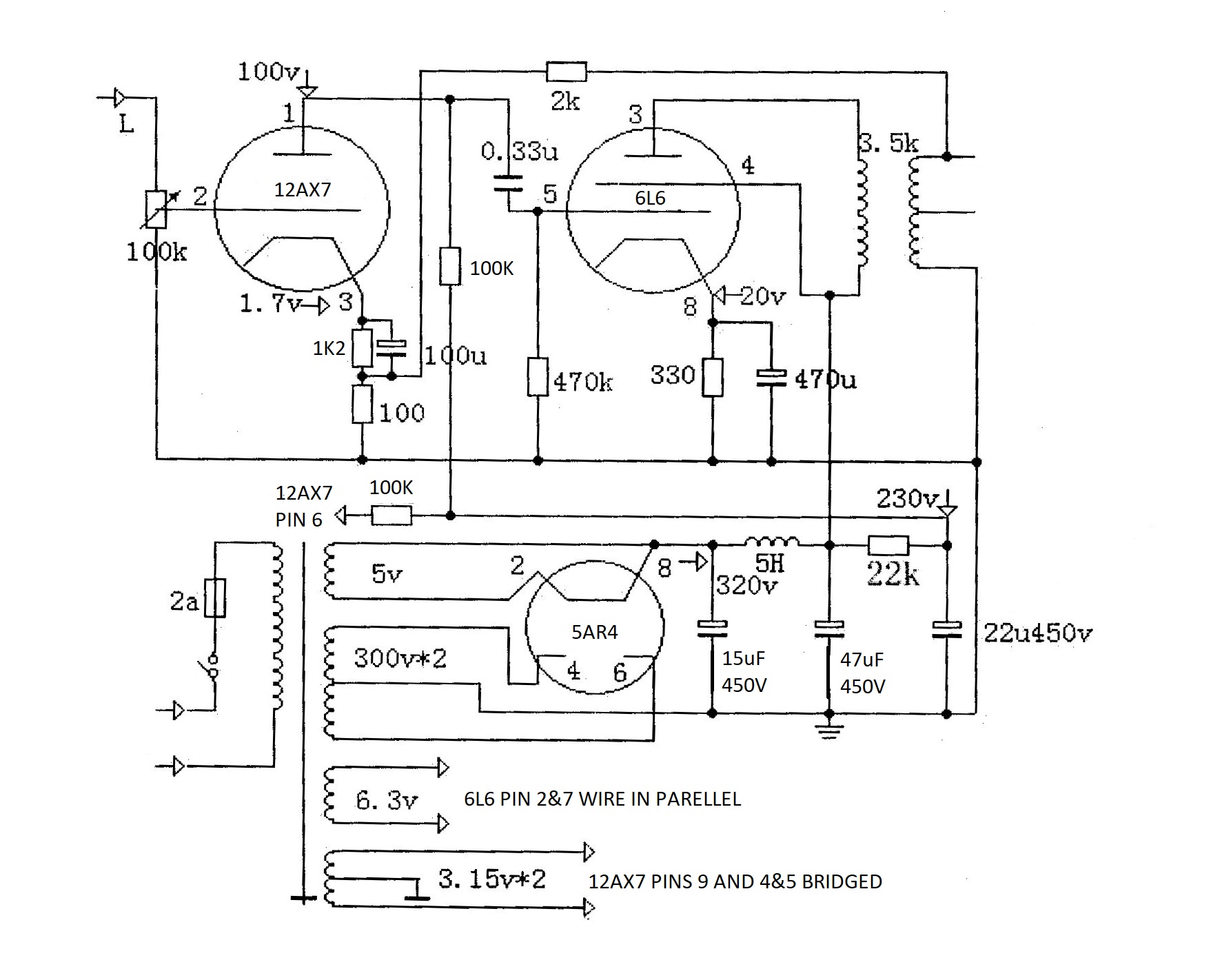
Does this look workable? is the 12AX7 suitable as the driver, would a 12AT7 be better? Should I still be looking for 100V on the Plates and 1.7V on the Cathodes?
also, purchased a NOS GE 5R4GB Tube without really knowing what I was buying. Derp. I think it will work as the rectifier in this amp, but if I were to build one for a friend I'd get a new 5AR4.
thanks!
I built the amp as drawn here and put a 5AR4 in the socket, along with a 12AX7 and a pair of 6L6, lookin' good:
hooked up a pair of speakers, turned it on, after 15 seconds a loud, high oscillation started, I saw arcing in the 5AR4, and the fuse went. Tore the whole thing apart, the only mistake I found was never connecting the signal ground to the main ground, and with that fixed I still get arcing in the 5AR4 about 15 seconds after powering on. So I figure that tube's done for.
The included schematic uses very large caps in the CLC circuit with a 5H choke. Most designs I've seen use much smaller caps, less than 20uF, so I think I'll move the 47uF to the 2nd position and put a 15uF in the 1st. I floated a question about this project on another thread and was advised to change the Plate and Cathode resistors for the driver tube to 100K and 1.2K, respectively. So I've made those changes to the drawing and translated what needed it.
Does this look workable? is the 12AX7 suitable as the driver, would a 12AT7 be better? Should I still be looking for 100V on the Plates and 1.7V on the Cathodes?
also, purchased a NOS GE 5R4GB Tube without really knowing what I was buying. Derp. I think it will work as the rectifier in this amp, but if I were to build one for a friend I'd get a new 5AR4.
thanks!
Attachments

Last edited:
Add a set off 1N4007 in series with the plates of the 5AR4, this eliminates the need to stand off the reverse voltage when the rectifier is not conducting and seems to reduce the likelihood of arcing.
Are you sure that you have phased the output transformer windings correctly - does it still oscillate? If so disconnect the feedback connections to the secondary and see if it is stable - if it is that indicates that you need to reverse either the primary or secondary output transformer connections.
I'd say the plate load resistor for the 12AX7 is on the low side given it's high rp. I would probably try a 150K resistor and make sure that you can swing at least 80Vpp linearly - if not adjust the 22K resistor to get enough voltage to do so.
The 12AT7 could be a good choice in this design given the low rp, but would need much more plate current and lower resistor values for plate and cathode.
Do you have an oscilloscope and function generator?
Your pictures need to be resized.. LOL I will get that seen to..
ya, couldn't figure out how to shrink em down.
OPT wires are Blue n Red, there's a label on the bottom, so unless they're connected wrong inside they're right. I'm avoiding silicone on this project so even those diodes are out. I know, I know.
What's rp ? I already have a couple different 12AX7 tubes, but no AT7s, so I'd rather stick with them for now. Of course, if it's a better end result, I'll order one tmrw.
I do have a oscilloscope and signal generator, in kit form, unassembled. Prob should get on that.
12ax7 has about 3 times more gain compared with 6n1, therefore you will have 3 times more Gnfb (global negative feedback). You should try with no NFB first and then increase feedback resistor from 2k to 5-10k. You also might want to connect a 100pF cap across feedback resistor see of oscillation is killed. However scope may be needed to be able to see the output (square) waveform use it as signal input.
Last edited:
- Status
- This old topic is closed. If you want to reopen this topic, contact a moderator using the "Report Post" button.
- Home
- Amplifiers
- Tubes / Valves
- Modding a Chinese 6P3P SE Amp kit for Western Tubes