When driving a speaker on a long cable, what is a safe capacitance to design an amplifier to be stable driving? Would 10 nF be a sufficient maximum capacitance or 100 nF? I measured some audio cable at about 400 pF/m, but I would guess that the variations in setups might produce higher capacitance loads. Are audio amps ever designed to be unconditionally stable with respect to capacitive loading, and if so, how? Given that oscillation of an amplifier could produce a catastrophic effect on a speaker if the amplitude was high enough, I would think this might be a consideration to maintain SOA.
VERY touchy subject !
This has split audio designers right down the middle just ask D.Self (or read his article in EW ) where in reply to several articles by another engineer cut him to ribbons by presenting an article "proving " that ring mains electric cable was just as good .
It didn't end there verbal fisticuffs ensued and the Editor had to calm things down .
Naim audio specified that their amps required special cables and that other types of cables could cause "problems ".
Those were the days of low capacitance cable/low inductive cable /low resistivity cable etc , from what I remember during the 80,s/90,s in EW .
I hope calmer minds are at work here as I was engrossed by each monthly episode of EW in the Letters & articles printed , things are a lot more duller now there.
Loudspeakers: Effects of amplifiers and cables – Part 4 | EE Times
Last edited:
Some people also say that some types of loudspeakers are themselves capacitive. So even if the cable length is 10 centimeters, the capacitance load driven by the amplifier is high.
One reason why some amplifier designers install an inductor in series between the amplifier output and the loudspeakers, is to improve stability when the load is capacitive. Other amplifier designers brag that they have no / need no series inductor.
One reason why some amplifier designers install an inductor in series between the amplifier output and the loudspeakers, is to improve stability when the load is capacitive. Other amplifier designers brag that they have no / need no series inductor.
simulation of C300 amplifier
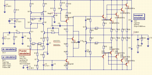
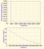
I am working on building up Michael Chua's C300 amplifier which does include a Zobel load on it. I have a SPICE simulation of it going. I am trying to figure out what could go wrong with it through simulation. I have been able to put 10 to 20 nF on it without problems, but once 100 nF is directly loaded on it, oscillations start. I can increase the Miller compensation capacitor to bring the pole down to be stable, but if the loop bandwidth is reduced too much, THD increases. It seems to be in the neighborhood of 0.05% to 0.1% for 20 kHz @ 200 W output to an 8 ohm load (at least in simulation).
The attached SPICE file is used with Qucs-S/ngspice and uses combinations of faster transistors to try to increase the loop bandwidth so that the dominant pole is the Miller capacitance. If anyone uses Qucs-S you can load this model up and try it for yourself.
This is why I need to have some idea of what a reasonable capacitance to design for is. 100 nF seems like a lot of capacitance for a cable, but perhaps someone has some ribbon-like audio cable that works that way.
Attachments
optimizing feedback
Unfortunately, there will always be a feedback arrangement that provides a bit less distortion at the price of stability. You have to do everything you can to stabilize your feedback and then look to other means to reduce distortion. For example, replacing R31+R32 with a single resistor and perhaps a capacitor (no connection to the final output) in order to cross-couple the drivers will improve the cross-over and high frequency performance.
C6 should be limited with a series resistor, 100 to 1k depending on R14. C6 causes RF rectification problems because it is a direct path from the speaker cable antenna to the LTP. C6 also exaggerates unpredictable problems that result from stray capacitance and inductance.
There are many complicated compensation methods but complicated compensation is vulnerable to unexpected variations that cause instability. My favorite plan is KISS, a single dominant pole. So I would not use R5+C3, and simply adjust C9 and/or R6...R10 until the circuit is stable.
Not using a series inductor +resistor in the output is leaving the feedback wide open vulnerable to all kinds of stability issues. I would only omit the inductor if the amp is integral to the speaker, ie no speaker cables to speak of, and the speaker impedances well defined.
"Not using a series inductor +resistor in the output is leaving the feedback wide open vulnerable to all kinds of stability issues. I would only omit the inductor if the amp is integral to the speaker, ie no speaker cables to speak of, and the speaker impedances well defined."
Definitely, who wants full power oscillation at 200kHz?
That lower distortion is illusory if it is only available along with conditional stability.
Definitely, who wants full power oscillation at 200kHz?
That lower distortion is illusory if it is only available along with conditional stability.
Last edited:
And yet none of the Nelson Pass designed power amps in the diyAudio Store, has an output inductor. Not one. Hundreds or perhaps thousands of diyAudio members have built these amps themselves, and none of them complain about full power oscillation at 200 kHz. No matter which speaker cables they use, no matter how long or how short are the speaker cables, no matter which loudspeakers they use.
I created the layout of the Nelson Pass "M2x" PCBs sold in the Store, and I promise you they don't have an output inductor ; they also don't have an RC Zobel network on the output. The schematics are linked on the sales page in the Store, have a look for yourself & don't take my word for it. M2x is 25W RMS per channel into 8 ohms.
However, and this is a huge red herring, the M2x amplifier in the Store DOES have a "4N25" optoisolator nestled within a negative feedback loop. This feedback loop sets the output stage bias current and keeps it constant regardless of air temperature or heatsink temperature. Practically none of the amplifiers with an output inductor, also have a 4N25 optoisolator. Which might or might not be significant.
_
Last edited:
Whether an inductor/zobel is needed is largely dependent on two main parameters: the slew rate and phase margin. As John Curl once mentioned, 100V/uS is the upper limit if you are careful with the stability issues. Of course the load has something to do with it, but for generic application this is a good guide.
So I tried to replace R31/R32 with a single resistor and capacitor, and it did not seem to change the distortion much at all (using the Fourier harmonic analysis).
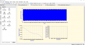
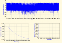
The oscillation that occurs in simulation never seems to be the full amplitude range of the power supply (+/- 70 VDC). Instead, it is usually +/-3 to +/-10 VDC. See the examples below. This occurs at an onset of 40 to 60 nF applied directly to the output of the design. If a 2 uH inductor/10 ohm resistor combination is applied before the capacitor, it is stable even though the output voltage is somewhat more distorted.
Perhaps the reason why this oscillation is not observed in practice is that cables are distributed capacitances and inductances, and so for example a meter of speaker cable is going on have on the order of 0.1 to 0.5 uH inductance anyways, so to have this amount of capacitance (10 nF or more) over this short distance the cable would have to be a long flat ribbon. Basically, the effective impedance of the cable would have to be extremely low (square root of inductance/length divided by capacitance/length) for the cable to act like a lumped capacitor at the terminals of the amplifier. Does this sound reasonable?
Looking at this passlabs web page the effective impedance of the "quality" audiophile cables is designed to be quite low, I think by weaving together the conductors to minimize loop size:
https://www.passlabs.com/technical_article/speaker-cables-science-or-snake-oil/
One question I would ask about the output inductor would be is how much the cable inductance itself acts to limit the oscillation, and this might explain if oscillation at the amplifier is not such as problem as it would be as if the speaker terminals are directly loaded with a capacitance.
Attachments
Given that oscillation of an amplifier could produce a catastrophic effect on a speaker if the amplitude was high enough, I would think this might be a consideration to maintain SOA.
If an amp oscillates it is at a very high frequency like 100kHz or higher. Also the amplitude is not full scale but "parasitic" rather 10%. The amp will get hot because of high dissipation also at 0-crossing where both the capacitive current and the voltage across the transistors are the highest.
This will not kill any speaker because the impedance is inductive and little current will flow at this frequency.
Speakers get killed by DC voltage or very low frequencies, but all amps have a detection and shut down hopefully.
A proper zobel network on the output can make the amp more stable, but bad board layout can not be cured so easily.
Nelson Pass amplifiers have a totally different philosophy. No attempt is made to achieve impressive distortion figures and feedback is minimal so stability is not a problem. It's more about "art" than technology. Nelson is playing with mostly FETs with no particular design objectives, a bit like abstract art. You like it, or not, and if you are looking for an amp with impressive specs then you can look else where. Nelson uses transistors capable of hundreds of watts to make 25W amps because blowing up your amp is no fun and the cost of parts is not an issue.
In my high school electronics lab there was a big old Heathkit tube amp. It was a mystery because it would simply burn connected speakers without making a sound. Years later, I realized it must have been oscillating at a super audible frequency. My guess is that the output transformer phase was wired wrong. The frequency was probably above the range of the scopes we used which had banana plug inputs.
Amplifier and cable impedance
The speaker cable is a sliding combination of inductance and capacitance. Cable design optimizes for a given balance, which can be frequency dependent. Cables that are optimized for low inductance (lLitz variety) are effectively converting that inductance to capacitance. So this is where some care is needed when the amplifier has no inductor in its output.
So a cable can appear almost as pure capacitor. The R of the cable is low. If there is no inductor, this represents almost a direct short of the amp output at some high frequency. The lower the output impedance of the amp, a function of feedback generally, determines where the stability break point occurs. Some determination of real world situation can be developed in simulation if a virtual cable is constructed as a segmented RCI combination.
The typical method in simulation is to use a load R in parallel with a range of capacitance and observe square wave ringing. It is personal choice that determines acceptable behavior. The amp may oscillate at some point, but if not a real world situation, decide if it matters.
JLH used many mosfet designs (which I built ) using only the inductance in the wirewound resistor I never experienced any ringing only had to take care of a bit of overshoot .
He actually made a point of this in his series of design philosophy pre actual build instructions in EW --1980,s.
While the inductance wasn't large it did work.
He actually made a point of this in his series of design philosophy pre actual build instructions in EW --1980,s.
While the inductance wasn't large it did work.
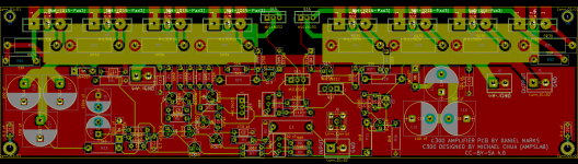
Another question: I laid out a board for the C300 and I made one side of the amp a ground plane (except for the TO-264 power transistors). I kept the lead lengths as short and wide as practical and kept room for the parts. I noticed that most audio amps don't use a ground plane, and for the most part are single-sided boards. Does putting in a ground plane cause a problem? I am used to designing RF stuff where the inductance is generally minimized by running a ground plane for the return currents, especially when closed loop feedback is used or the inductance of the ground plane connection would cause oscillation.
If you look at the layout of the board, the red is the top layer, the green is the bottom layer, and yellow is the two layers together. I made the top layer ground for most of the board, and where the transistors are, I made the layers the output and the +/- VDC rails to try to minimize inductance. The trace that is between the two sides of the AB amplifier is 4 mm wide. Also, I use 100 nF capacitors to AC couple the ground plane to the chassis to reduce noise, as well as use power conditioning on the input power (two layers of film capacitor filtering and common-mode chokes). I think these are good design practices, at least for RF which I am more used to laying out.
If you look at the layout of the board, the red is the top layer, the green is the bottom layer, and yellow is the two layers together. I made the top layer ground for most of the board, and where the transistors are, I made the layers the output and the +/- VDC rails to try to minimize inductance. The trace that is between the two sides of the AB amplifier is 4 mm wide. Also, I use 100 nF capacitors to AC couple the ground plane to the chassis to reduce noise, as well as use power conditioning on the input power (two layers of film capacitor filtering and common-mode chokes). I think these are good design practices, at least for RF which I am more used to laying out.
Attachments
The reason feedback amplifies oscillate with a capacitive load can be explained by considering what happens as you apply compensation around the amp. Normally you have two poles - one at a few hundred to a few kHz, and another up at a few hundred kHz to perhaps a MHz or so. When you come the amp, the poles move apart - one will move down in frequency and the other up in frequency so that it lies below 0dB and with less than 180 degree phase shift (usually you set it so you have 60+ degree phase margin).
If you then apply a capacitive load to the output of the amplifier, the upper pole moves down in frequency. If it moves down far enough (easy to do in practice) the gain at the second pole rises above 0 dB and you have instability.
The cure in almost all cases is to place a small inductor in series with the amplifier output (‘output coupling inductor’). Using modern high fT devices, anything more than 0.6 uH almost always does the trick.
Output Coupling Inductors
- Status
- This old topic is closed. If you want to reopen this topic, contact a moderator using the "Report Post" button.
- Home
- Amplifiers
- Solid State
- Stability of an amplifier under capacitive loading