Hi,
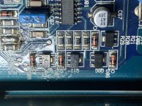
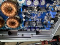
Got in a crossfire vr4000d in protect. No shorted FETs, I’m working through the power supply I found some shorted drivers. I can’t seem to find info on these, anyone got correct numbers, or subs?
DY 411
Got in a crossfire vr4000d in protect. No shorted FETs, I’m working through the power supply I found some shorted drivers. I can’t seem to find info on these, anyone got correct numbers, or subs?
DY 411
Attachments
Thanks perry!
I got the drivers sorted, and moved along troubleshooting.
Testing the voltages on the output of the 339, I found pin 2 was ‘high’ it measured 2.21v.
Looking at the inputs, I have 4.81v on pin 4 and 5.01v on pin 5. If I short pins 4 and 5 together I get the amp to power up.
Pins 5 and 6 are tied together so they should be the reference side. Im following the circuit through the components But they appear at first testing to be ok.
Any suggestions?
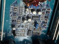
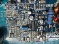
I did a search, but not much info on these amps. The driver boards have the DIl4060 chips.
Attachments

I believe 7 amps is excessive at this point with protection on.
- I don’t have a gate drive signal coming out the 494,
- I don’t have a sawtooth on pin 5 of the 494,
- I have reference 5v on pins 13,14,15
If short I pins 4 and 5 of the 339:
- the protect light goes off,
- the transformers begin to get warm a bit,
- the sawtooth comes up at pin 5 of the 494,
- I measured a faint 1.92v with the scope at the FET gate.
I measured the dc voltages of both chips:
494
1. 0.021
2 4.920
3. 0.058
4. 3.070
5. 1.450
6. 3.631
7. 0.002
8. 11.02
9. 0.930
10. 0.131
11. 10.99
12. 10.99
13. 4.92
14. 4.92
15. 4.92
16. 0.015
339:
1. 0.112
2. 0.705
3. 11.34
4. 5.574
5. 4.742
6. 4.742
7. 3.360
8. 4.34
9. 2.329
10. 0.042
11. 0.002
12. 0.002
13. 0.038
14. 0.113
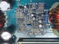
I’ve attached a pic of the PS control Section, it seems pin 3 of the 494 is not connected/being used as an input.
Looking back at the dc voltages of the 339 it seems I have other faults.
When the amp came in it had c31 blown apart. I believe this to be a snubber on the secondary side of the transformer and not affect the troubleshooting, I have not sourced or replaced this to this point.
- I don’t have a gate drive signal coming out the 494,
- I don’t have a sawtooth on pin 5 of the 494,
- I have reference 5v on pins 13,14,15
If short I pins 4 and 5 of the 339:
- the protect light goes off,
- the transformers begin to get warm a bit,
- the sawtooth comes up at pin 5 of the 494,
- I measured a faint 1.92v with the scope at the FET gate.
I measured the dc voltages of both chips:
494
1. 0.021
2 4.920
3. 0.058
4. 3.070
5. 1.450
6. 3.631
7. 0.002
8. 11.02
9. 0.930
10. 0.131
11. 10.99
12. 10.99
13. 4.92
14. 4.92
15. 4.92
16. 0.015
339:
1. 0.112
2. 0.705
3. 11.34
4. 5.574
5. 4.742
6. 4.742
7. 3.360
8. 4.34
9. 2.329
10. 0.042
11. 0.002
12. 0.002
13. 0.038
14. 0.113
I’ve attached a pic of the PS control Section, it seems pin 3 of the 494 is not connected/being used as an input.
Looking back at the dc voltages of the 339 it seems I have other faults.
When the amp came in it had c31 blown apart. I believe this to be a snubber on the secondary side of the transformer and not affect the troubleshooting, I have not sourced or replaced this to this point.
Attachments
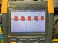
Hold on, I think I have something happening on the drive circuitry. With pin 9 and 10 out the circuit, I have square waves.
Reviewing pins 1 and 2, I should be getting output, I lifted 9 and 10 and I have square waves on both.
Do you know of other replacements for the DY 411? I got some surface mount diodes around those transistors, they’re testing good but Incase I do find something.
Reviewing pins 1 and 2, I should be getting output, I lifted 9 and 10 and I have square waves on both.
Do you know of other replacements for the DY 411? I got some surface mount diodes around those transistors, they’re testing good but Incase I do find something.
- Home
- General Interest
- Car Audio
- Crossfire vr4000d