Hi,
I'm curious about the impedance curve of my new esl panels. I have REW installed on my laptop, but my laptop has only a mic out jack, no line inputs. I would like to use this scheme:
https://www.roomeqwizard.com/help/images/impedancesetup.jpg
I'm wondering what would be a good way to make a impedance plot with my laptop + REW: would an external USB soundcard with line input and mic output work? Something like this soundcard:
Product
Last edited:
I suppose you are talking of the low-voltage side of the step-up transformer.
I'm not sure how REW instructs you to do it, but here's my variation. Test a few resistors in place of where the speaker would be (takes 30 seconds to change resistors and run a sweep). The values should cover the range of the speaker, like 40 Ohms down to 2 Ohms.
Then when you plot the speaker resistance, you'll have some curves to include on the plot as trustworthy benchmarks.
Here's an example (fourth plot in post #1) with a labyrinth speaker. And it illustrates why a benchmark is a good idea (I don't know why the curve droops in the bass but I trust it is the true state of affairs with my measurement system that day).
17 foot pipe sub 12-230 Hz ±5dB
B.
Last edited:
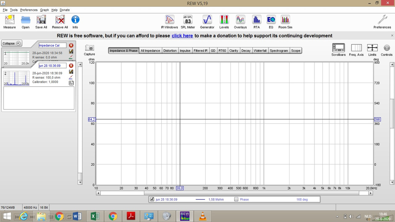
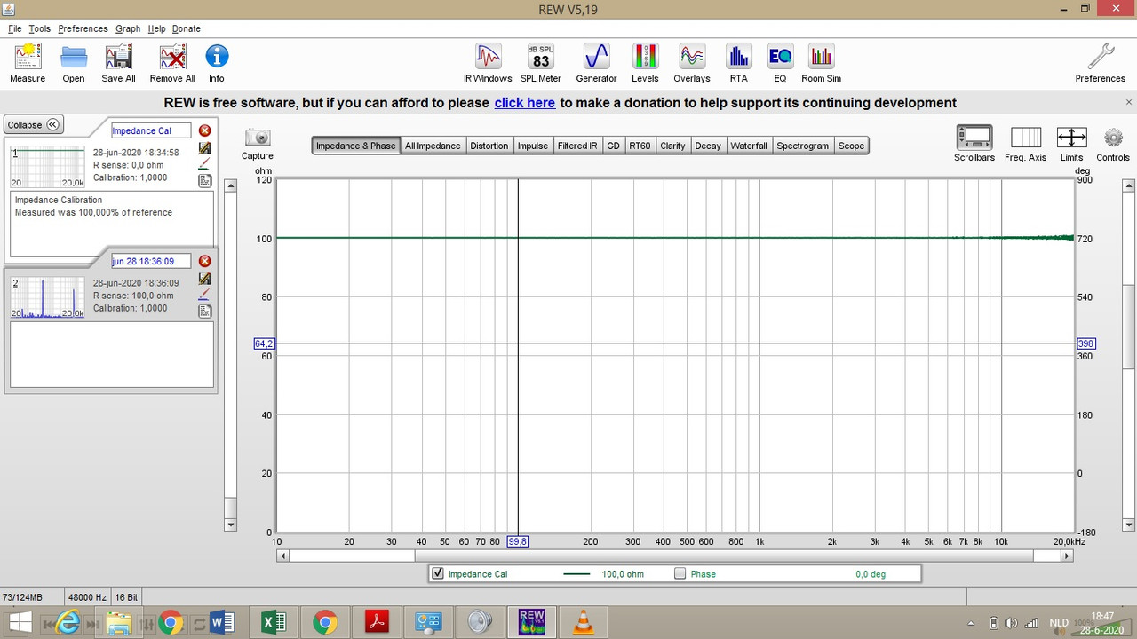
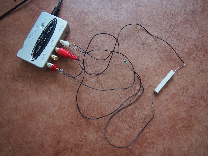
Hi, thanks for your suggesions! I just tried to do an impedance measurent, but unfortunately I ran into a lot of problems. On my mac it didn't work at all, but on a Windows laptop I got some bad measurement results: although I selected the USB audio codec as input and output, and I did a callibration beforehand, I still got unreliable results: impedance values of 1.58 M-Ohms. I attached some screenshots and a picture of my gear. It looks messy, but I used this scheme: https://www.roomeqwizard.com/help/images/impedancesetup.jpg
I used a 100 Ohms sense resistor and I used a 0,33 Ohms load resistor.
First I used the headphone output, but as this didn't work I tried the RCA output instead - also with bad results. Do you have any idea what could be wrong? Should I try the asio driver instead? Is there an error in my hardware scheme?
Last edited:
Not quite sure what you did, but the impedance is based on a large resistor (say, 200 Ohms) in series with the device under test (say 70 Ohms or 2 Ohms). You are trying to see the reading you get across the little resistor (and later, substituting the speaker for the little resistor).
With my empirical method, there's no calibration. You just want the FR to register in a useful working band. The 70 and the 2 are your benchmarks. Then you plot all the curves together on the REW screen that puts various curves on the same framework.
Your headphone output should work OK. Unshielded alligator clips leading into your DAC are also OK if the load is just 70 Ohms or less.
B.
Last edited:
For best fidelity of impedance measurement, you would use an amplifier with a 10ohm or lower sense resistor. I have also had good luck with a 47ohm sense resistor when using the headphones output. Make sure you have the mechanical volume control for the headphones on the unit turned all the way up.
But, before optimizing your setup, you can work with the Lineout setup that you have wired up right now. For easier troubleshooting, I would recommend a higher load resistor than 0.33ohm …something in the 4 – 10 ohm range to avoid confusion with wiring resistance.
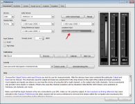
First, check your Preferences to make sure you have something selected for both the Input and the Loopback input. My guess is that nothing is selected for the Loopback. (see Pic #1) The channel that is selected for “Input” on the Preferences window should be the same one you choose as Input on the Impedance measurement window. This is the channel that will be connected to the junction of the load and sense resistor. Note that if you change channel selection on the Impedance window, sometimes you have to go back to the Preferences window and reselect the Loopback input…always good to double-check the selection before Calibration or measurement.
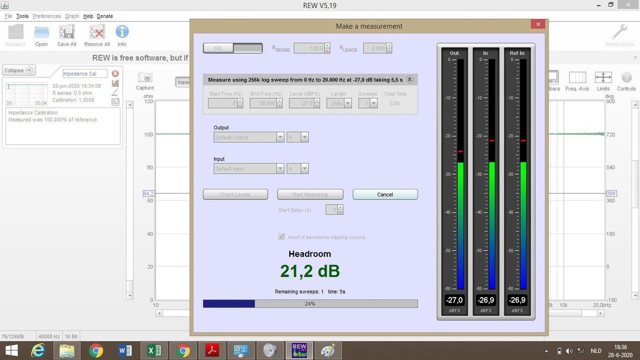
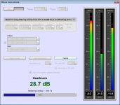
When taking a measurement, you should always see the “In” Level to be lower than the “RefIn” level since there is a voltage drop across the sense resistor. (see Pic #2) If you see “In” level higher than “RefIn” then you need to swap your input channels, either physically, or in the software on the Impedance measurement window.
Hopefully these few suggestions will get you reasonable results for measuring components with known impedances. Once you get that, then you can move on to measuring your ESL.
But, before optimizing your setup, you can work with the Lineout setup that you have wired up right now. For easier troubleshooting, I would recommend a higher load resistor than 0.33ohm …something in the 4 – 10 ohm range to avoid confusion with wiring resistance.
First, check your Preferences to make sure you have something selected for both the Input and the Loopback input. My guess is that nothing is selected for the Loopback. (see Pic #1) The channel that is selected for “Input” on the Preferences window should be the same one you choose as Input on the Impedance measurement window. This is the channel that will be connected to the junction of the load and sense resistor. Note that if you change channel selection on the Impedance window, sometimes you have to go back to the Preferences window and reselect the Loopback input…always good to double-check the selection before Calibration or measurement.
When taking a measurement, you should always see the “In” Level to be lower than the “RefIn” level since there is a voltage drop across the sense resistor. (see Pic #2) If you see “In” level higher than “RefIn” then you need to swap your input channels, either physically, or in the software on the Impedance measurement window.
Hopefully these few suggestions will get you reasonable results for measuring components with known impedances. Once you get that, then you can move on to measuring your ESL.
Attachments
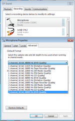
I just realized you are probably not using an ASIO driver option like I am. For reference, I use the ASIO4ALL universal AISO driver with the UCA202. If you are using the Java driver and select the USB audio codec, you might double check the recording mixer panel to make sure the USB microphone is set up for 2 channel operation. Often the default is set to 1 channel. In that case, REW would be receiving the L channel information for both the L and R signals it uses and you could get the high impedance results like you were showing.… I selected the USB audio codec as input and output
Attachments
Hi, thanks for your quick and helpful responses! I tried the two channel option as well, but I remember getting no input measurement in REW at all after selecting this option. I will retry that option again and also check the other options like the ASIO4ALL driver, checking the loopback channel etc.!
For best fidelity of impedance measurement, you would use an amplifier with a 10ohm or lower sense resistor. I have also had good luck with a 47ohm sense resistor when using the headphones output. Make sure you have the mechanical volume control for the headphones on the unit turned all the way up.
Do you recommend a lower than 100 ohm sense resistor (like 10 to 47 ohm) in combination with the line-out output on the external soundcard?
I will try a 6 - 10 ohm load.
Hi There, Been a while since I have posted any thing. ")
I have much experience in the past with this sort of thing.
Even though it is quite easy to do such measurements with sound cards, in order to get the most accurate results of your time doing so you really should use some buffers between your sound card and the device you are measuring, ie ESL's, Step up transformer's and Caps and such.
For a few reasons,
#1 First and foremost they isolate the sound cards impedances from the device that you are trying to measure.
This including any cable impedances connect to the soundcard and are isolated from the measurement of the device across the reference resistor.
Even the slightest loading can cause a pretty large error as I have found out first hand.
Sorry, but I don't have my graphs handy anymore as they were all produced and posted to the ESL DIY website that is now defunct and now all gone.
Some of those graphs can be found here but my whole tutorial on the subject has disappeared unfortunately as it was a lot of work and great info for all.
#2 They help to provide some protection to the I/O of your sound card.
With my techniques I was able to measure my Step up transformer directly from its output of 4-5KV peak straight in to a brand new (At the time) Asrock 990FX Extreme 4 motherboard and later I started using my GINA24 sound card with no damage to either system (still using them to this day).
In fact with this method I did post some measurements of the testing of the Antek 1206 transformers that everyone started using at the time as it failed and shorted out.
I was lucky enough to repair the transformer and continue testing and those can be found somewhere in these threads.
#3 The sense resistor should be rather low if you plan on taking the measurement with the step up transformer.
The reason being is that any added resistance in the primary circuit effect's the overall impedance curve and Frequency response of the panel output.
Even as much as 1 or 2 ohms can drastically change FR most notably at the Transformer resonance peak on the high end due to the transformer's leakage inductance and transformer's parasitic and panel capacitance added together.
This is a known fact I am sure that you are aware of.
Therefore using a .1 ohm resistance and a buffer opamp with a gain of 10 will give you 1 volt reading across the .1 ohm resistor for 1 amp of current while providing a minimum amount of loading of the primary winding under test.
If you are just testing the panel then yes you could use a higher value.
But you still need to drive the panel with a low impedance buffer even if it is only at a 1 or 2 volt level.
Now as far as that actual resistance, Well I have had issues with measurements not being exactly the same while using different values for the reference resistor with the exact same device being tested.
Why? .... I have not had the time to investigate why this is.
Even though the measurements were pretty much in the ball park to one another, overall, it was the peak of the impedance curve that would change with the value of the reference resistor all else staying the same per test.
Probably not a big deal but I was aiming to get the most accurate results that I could.
See this thread on this issue,
New speaker impedance tool, SimpeS
New speaker impedance tool, SimpeS
New speaker impedance tool, SimpeS
REW and SimpleS had just employed impedance measurements at the time I was doing this and I have not revisited them since then (or anything for that matter I've just been to busy lately).
I was using Visual Analyser for all of my testing for the most part at the time, it is a great tool if your machine has the power to handle it.
A thread on this very subject is found here,
How to measure capacitor impedance graph
In post #4 are links to the interface and VA that I used,.
Most any decent opamp will work just fine, I just happened to have some excellent ones from LT that I use.
I see VA has been updated since then and I have not tried out the newest version yet, It has all those needed functions built right into it as well, It is an amazing piece of software !!
As far as driving the test unit a good quality audio amp may be used, but not all are DC stable with such a low DC resistance as a load.
My Crown DC 300A worked okay but it was sketchy getting it to work properly at time due to such a low DC resistance load.
For my testing I had made my own high power non-inductance 1 ohm reference resistor out of out of about 30 feet of West Penn balanced cable all folded up.
Since it was made of copper it did change slightly as it heated up but not to bad.
It was during the winter time when I was doing this so I just dropped the dummy load out the window to keep it cool and that kept from burning up, it worked great and got the job done !
As for my buffer I used the Crown to drive my transformer tests when it was meant to be at a high power.
For all other tests for just measuring stuff I came up with nice little DC stable amp using an LT1210.
This allowed me to have something that could handle a very low impedance while only driving with a 1-4 volt peak signal as that is all that is needed.
That circuit is found here,
How to measure capacitor impedance graph
I never did build a proper PCB for it yet but I was amazed that the thing worked as well as it did on just an old cruddy protoboard, Thanks to the DC servo loop employed in it.
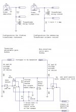
Here is Version 1 of my test jig,
Step-up transformer design
Attached is a detailed sheet of my test jig.
Cheers !!

Keep on DIYin' !!
jer
P.S. to save time here is the link to the impedance jig I use.
http://wb6dhw.com/RLC_Meter.html
I have much experience in the past with this sort of thing.
Even though it is quite easy to do such measurements with sound cards, in order to get the most accurate results of your time doing so you really should use some buffers between your sound card and the device you are measuring, ie ESL's, Step up transformer's and Caps and such.
For a few reasons,
#1 First and foremost they isolate the sound cards impedances from the device that you are trying to measure.
This including any cable impedances connect to the soundcard and are isolated from the measurement of the device across the reference resistor.
Even the slightest loading can cause a pretty large error as I have found out first hand.
Sorry, but I don't have my graphs handy anymore as they were all produced and posted to the ESL DIY website that is now defunct and now all gone.
Some of those graphs can be found here but my whole tutorial on the subject has disappeared unfortunately as it was a lot of work and great info for all.
#2 They help to provide some protection to the I/O of your sound card.
With my techniques I was able to measure my Step up transformer directly from its output of 4-5KV peak straight in to a brand new (At the time) Asrock 990FX Extreme 4 motherboard and later I started using my GINA24 sound card with no damage to either system (still using them to this day).
In fact with this method I did post some measurements of the testing of the Antek 1206 transformers that everyone started using at the time as it failed and shorted out.
I was lucky enough to repair the transformer and continue testing and those can be found somewhere in these threads.
#3 The sense resistor should be rather low if you plan on taking the measurement with the step up transformer.
The reason being is that any added resistance in the primary circuit effect's the overall impedance curve and Frequency response of the panel output.
Even as much as 1 or 2 ohms can drastically change FR most notably at the Transformer resonance peak on the high end due to the transformer's leakage inductance and transformer's parasitic and panel capacitance added together.
This is a known fact I am sure that you are aware of.
Therefore using a .1 ohm resistance and a buffer opamp with a gain of 10 will give you 1 volt reading across the .1 ohm resistor for 1 amp of current while providing a minimum amount of loading of the primary winding under test.
If you are just testing the panel then yes you could use a higher value.
But you still need to drive the panel with a low impedance buffer even if it is only at a 1 or 2 volt level.
Now as far as that actual resistance, Well I have had issues with measurements not being exactly the same while using different values for the reference resistor with the exact same device being tested.
Why? .... I have not had the time to investigate why this is.
Even though the measurements were pretty much in the ball park to one another, overall, it was the peak of the impedance curve that would change with the value of the reference resistor all else staying the same per test.
Probably not a big deal but I was aiming to get the most accurate results that I could.
See this thread on this issue,
New speaker impedance tool, SimpeS
New speaker impedance tool, SimpeS
New speaker impedance tool, SimpeS
REW and SimpleS had just employed impedance measurements at the time I was doing this and I have not revisited them since then (or anything for that matter I've just been to busy lately).
I was using Visual Analyser for all of my testing for the most part at the time, it is a great tool if your machine has the power to handle it.
A thread on this very subject is found here,
How to measure capacitor impedance graph
In post #4 are links to the interface and VA that I used,.
Most any decent opamp will work just fine, I just happened to have some excellent ones from LT that I use.
I see VA has been updated since then and I have not tried out the newest version yet, It has all those needed functions built right into it as well, It is an amazing piece of software !!
As far as driving the test unit a good quality audio amp may be used, but not all are DC stable with such a low DC resistance as a load.
My Crown DC 300A worked okay but it was sketchy getting it to work properly at time due to such a low DC resistance load.
For my testing I had made my own high power non-inductance 1 ohm reference resistor out of out of about 30 feet of West Penn balanced cable all folded up.
Since it was made of copper it did change slightly as it heated up but not to bad.
It was during the winter time when I was doing this so I just dropped the dummy load out the window to keep it cool and that kept from burning up, it worked great and got the job done !
As for my buffer I used the Crown to drive my transformer tests when it was meant to be at a high power.
For all other tests for just measuring stuff I came up with nice little DC stable amp using an LT1210.
This allowed me to have something that could handle a very low impedance while only driving with a 1-4 volt peak signal as that is all that is needed.
That circuit is found here,
How to measure capacitor impedance graph
I never did build a proper PCB for it yet but I was amazed that the thing worked as well as it did on just an old cruddy protoboard, Thanks to the DC servo loop employed in it.
Here is Version 1 of my test jig,
Step-up transformer design
Attached is a detailed sheet of my test jig.
Cheers !!
Keep on DIYin' !!
jer
P.S. to save time here is the link to the impedance jig I use.
http://wb6dhw.com/RLC_Meter.html
Attachments
Last edited:
Gerald, thanks for the overview. I am lucky to have access to a Bode 100 so the measurements are a no-brainer, and I used a small audio amplifier to drive the xover filter.
But I did find out (thanks to member vacuphile) that it was probably wrong to leave off the woofer load when measuring the xover impedance. There is some series resonant circuitry in it which leads to a very low measured minimum impedance of less than 2 ohms.
Paul pointed out that the parallel impedance of the woofer would damp that resonance and probably would lead to a higher minimum impedance. Counter-intuitive, but makes sense.
So I'll re-do my measurement with a nominal 8 or 6 ohms parallel load included.
Jan
Last edited:
It kinda sounds like a series orientated crossover, I had started on such a design a while back for my desktop ESL using the primary inductance of the transformer as a filter for the woofer.
It was a really cool design and was looking pretty good in the sim's but it required a lot of big caps and no way was I going to use electrolytics in it.
I really wasn't to happy at what it was doing to phase response of the signal either, it looked pretty sloppy, actually the phase was changing all over the place across the whole bandwidth, so I dropped the idea and started working on some direct drive circuits instead that would probably cost less for the whole amp compared to what the caps cost.
jer
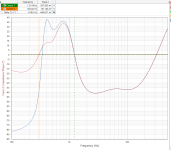
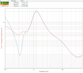
As much as I hate to admit, Paul was right: with the woofer connected, through it's own xover, the imput impedance of the combination now stays above 5R. Without the woofer it dipped below 2R.
See attached graphs, blue without woofer (I used an 8R resistor as 'woofer' for the measurements).
Jan
See attached graphs, blue without woofer (I used an 8R resistor as 'woofer' for the measurements).
Jan
Attachments
You really should stick in a resistor of 5 Ohms and see how that plots.
Fry's top left diagram and my posts 2 and 6 are simple and direct. Any sound card or the little DAC is (or should be) designed to drive headphones. So, as long as the load is over 40 Ohms, their output will be fine for your tests... esp if you use the benchmark approach of post 2.
With a benchmark, you can see how your measurement system is working. Without it, you are flying on unverified assumptions.
The ML XO is interesting. There is a series resistor for the woofer - maybe to add tubbiness at resonance or trim loudness. As usual, the ESL XO has necessary protective resistors.
B.
Last edited:
As much as I hate to admit, Paul was right: with the woofer connected, through it's own xover, the imput impedance of the combination now stays above 5R. Without the woofer it dipped below 2R
Missed it on first reading: how can the impedance be higher with the woofer connected? Isn't the woofer in parallel with the tweeter? Can you educate me, please.
B.
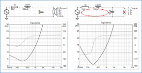
If you look at the woofer crossover, you can see that if the woofer is removed you are left with a series resonant circuit. At resonance the impedance will dip to the series resistance of the circuit loop which in the attached example is about 1.25 ohm. Adding an 8 ohm load in parallel with the capacitor provides some amount of damping, thus increasing the impedance at the resonance frequency. Of course below resonance the impedance is reduced with the added 8 ohm load, in line with intuition.
This behavior is seen with most 2nd order crossovers(HP or LP) when measuring without a load, unless the series padding resistor used for level matching is of a high enough value to mask the effect.
This behavior is seen with most 2nd order crossovers(HP or LP) when measuring without a load, unless the series padding resistor used for level matching is of a high enough value to mask the effect.
Attachments
- Status
- This old topic is closed. If you want to reopen this topic, contact a moderator using the "Report Post" button.
- Home
- Loudspeakers
- Planars & Exotics
- esl impedance measurement