Hello
I was using for a long time an amanero connected with cronus to a b3se 9018 dac. The dac is controlled by an external controller that supports volume control and other registry changes by remote and also rotary encoder, displays correct sampling rate for pcm signals, for dsd it shows only that dsd is played.
On my pc I use foobar to upsample pcm signals to 352/384khz and bypass dsd(actually dsd128 and dsd256 are downsampled to dsd64 because with the higher dsd rates I have dropouts).
Because the cpu of my pc runs quite hot when I run foobar with upsampling I thought to use an external src like ak4137 and see how things go.
There was another reason that made me think about an external src. I use a remote on my dac to control the volume and to switch on/off the oversampling filter. When I play pcm signals at 352/384khz I need to have oversampling off, when I play dsd signals oversampling needs to be on.
If I use the src to send only dsd or only pcm signals to the dac then I won`t need to use the remote to switch on/off oversampling. And since I also plan for a separate preamp I won`t need the volume control on the dac so in one word I could place back the original mcu of the b3se dac and simplify things a lot by removing the external controller.
This way the dac will become a very simple unit that will need to be turned only on/off.
One day reading in the ES9038Q2M Board thread I have seen some posts from user Markw4 about ak4137 src. After reading a bit about what the chip can do and also seeing that you can buy a new src board with 30$ I decided to give it a try.
After I ordered the board I suddenly had some doubts about where the ak4137 should be integrated, first or after the cronus reclocker. So I decided to send a private message to Markw4 and ask for an advice.
As a reply I got this
First of all I have to say that I have one of the first versions of cronus that doesn`t have a buffer on the master clock line.
Second thing, when you start the src board and hold down the select button you can choose between amanero or xmos how Markw4 says. The only difference I noticed when selecting one or the other was that when selecting amanero I get as input sample rate on the src display "other" and when I set for xmos I get "44.1khz" for all the frequencies that I input.
I have no problems with this since I plan to use the src board without its display.
Once I got the src board I connected it as Markw4 said. When getting the divided clock for amanero and ak4137 I didn`t add the buffer but instead I added another 33ohm resistor on the clock divider output(photo 1). One resistor(original one) transports the clock to amanero and the added resistor transports the clock to the ak4137 board(photo 2 and 3).
Initially this didn`t work because I had inverted some connections(photo 4).
The ldo for the clocks on the src board was removed and also the resistors on the outputs of the oscillators were removed(photo 5)
Seeing that it`s not working I decided to connect first the src to amanero directly to see how it works.
To do this I had to replace the connector on the src board. Amanero had a female connector and the src had also a female connector so I decided to replace it on the src with a male connector. Since I was already there I decided to replace also the output connector with a more decent one") This gave me the possibility to take some photos of how the connections are under the connectors(photo 6 and 7).
This gave me the possibility to take some photos of how the connections are under the connectors(photo 6 and 7).
All measurements were done with the dac ouput used in voltage mode. I have some 100R(if I remember correctly) resistors connected on each b3se output.
Connected to amanero directly I managed to play pcm and dsd files and also to take some measurements with rew and a scarlett 2i2 soundcard. Please notice that there is a measurement artifact ~14khz. When I use the isolator after amanero this artifact disappears.
My test samples are 48k wav files which are played from foobar with asio.
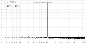
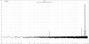
In all the cases input sampling frequency in the src board was 48k.
Photo 8 shows src output pcm at 384khz and 1khz signal on output
Photo 9 shows src output pcm at 384khz and 13 & 14khz signal on output
Photo 10 shows src output pcm at 384khz and 19 & 20khz signal on output
I was using for a long time an amanero connected with cronus to a b3se 9018 dac. The dac is controlled by an external controller that supports volume control and other registry changes by remote and also rotary encoder, displays correct sampling rate for pcm signals, for dsd it shows only that dsd is played.
On my pc I use foobar to upsample pcm signals to 352/384khz and bypass dsd(actually dsd128 and dsd256 are downsampled to dsd64 because with the higher dsd rates I have dropouts).
Because the cpu of my pc runs quite hot when I run foobar with upsampling I thought to use an external src like ak4137 and see how things go.
There was another reason that made me think about an external src. I use a remote on my dac to control the volume and to switch on/off the oversampling filter. When I play pcm signals at 352/384khz I need to have oversampling off, when I play dsd signals oversampling needs to be on.
If I use the src to send only dsd or only pcm signals to the dac then I won`t need to use the remote to switch on/off oversampling. And since I also plan for a separate preamp I won`t need the volume control on the dac so in one word I could place back the original mcu of the b3se dac and simplify things a lot by removing the external controller.
This way the dac will become a very simple unit that will need to be turned only on/off.
One day reading in the ES9038Q2M Board thread I have seen some posts from user Markw4 about ak4137 src. After reading a bit about what the chip can do and also seeing that you can buy a new src board with 30$ I decided to give it a try.
After I ordered the board I suddenly had some doubts about where the ak4137 should be integrated, first or after the cronus reclocker. So I decided to send a private message to Markw4 and ask for an advice.
As a reply I got this
Markw4 said:Hi,
With newer Cronus boards the two 8-pin dips are a clock divider for the Amanaero, and a MCLK buffer, IIRC.
Yes, AK4137 needs the same frequencies as Amanero, but a buffer should be used to create a new copy of the clock for Amanero. A 33-ohm resistor should be connected in series with one output which would then go to AK4137, after its clocks have been disabled by cutting the power trace.
I2S signals, BCLK, LRCK, and DATA from Cronus must be routed to AK4137 inputs. Firmware in the ASRC board can be set to XMOS or Amaero mode by holding down the select button at power on. Don't know what difference it makes. That particular ASRC board may or may not mute the output until you change one of the settings such as output sample rate. If so, its looking for Amanero signals it doesn't have such as mute or F0-F3, and or DSD_ON. Only way to fix that I know of offhand would be to take over control of ASRC board over I2C with something like an Amanero. I can provide advice and some sample code to tweak registers, etc.
First of all I have to say that I have one of the first versions of cronus that doesn`t have a buffer on the master clock line.
Second thing, when you start the src board and hold down the select button you can choose between amanero or xmos how Markw4 says. The only difference I noticed when selecting one or the other was that when selecting amanero I get as input sample rate on the src display "other" and when I set for xmos I get "44.1khz" for all the frequencies that I input.
I have no problems with this since I plan to use the src board without its display.
Once I got the src board I connected it as Markw4 said. When getting the divided clock for amanero and ak4137 I didn`t add the buffer but instead I added another 33ohm resistor on the clock divider output(photo 1). One resistor(original one) transports the clock to amanero and the added resistor transports the clock to the ak4137 board(photo 2 and 3).
Initially this didn`t work because I had inverted some connections(photo 4).
The ldo for the clocks on the src board was removed and also the resistors on the outputs of the oscillators were removed(photo 5)
Seeing that it`s not working I decided to connect first the src to amanero directly to see how it works.
To do this I had to replace the connector on the src board. Amanero had a female connector and the src had also a female connector so I decided to replace it on the src with a male connector. Since I was already there I decided to replace also the output connector with a more decent one
This gave me the possibility to take some photos of how the connections are under the connectors(photo 6 and 7).All measurements were done with the dac ouput used in voltage mode. I have some 100R(if I remember correctly) resistors connected on each b3se output.
Connected to amanero directly I managed to play pcm and dsd files and also to take some measurements with rew and a scarlett 2i2 soundcard. Please notice that there is a measurement artifact ~14khz. When I use the isolator after amanero this artifact disappears.
My test samples are 48k wav files which are played from foobar with asio.
In all the cases input sampling frequency in the src board was 48k.
Photo 8 shows src output pcm at 384khz and 1khz signal on output
Photo 9 shows src output pcm at 384khz and 13 & 14khz signal on output
Photo 10 shows src output pcm at 384khz and 19 & 20khz signal on output
Attachments
-
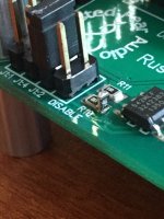 image3.jpeg122.7 KB · Views: 443
 -
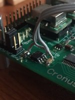 image8.jpeg120.3 KB · Views: 432
 -
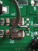 image6.jpeg127.1 KB · Views: 433
 -
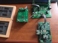 image7.jpeg134.1 KB · Views: 435
 -
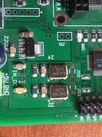 image2.jpeg155.5 KB · Views: 434
 -
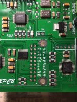 image9.jpeg173.9 KB · Views: 183
 -
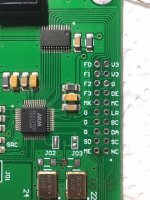 image11.jpeg145.3 KB · Views: 184
 -
 ak4137 in 48khz out 384khz b3se osfoff.jpg142.1 KB · Views: 184
 -
 ak4137 pcm 48khz in 384khz out 13&14khz.jpg132.6 KB · Views: 150
 -
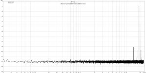 ak4137 pcm 48khz in 384khz out.jpg130.9 KB · Views: 128
Same input sample rate to the src but this time the output was dsd128
Photo 1 shows 1khz signal, photo 2 13 & 14khz signals, photo 3 19 & 20khz signals.
If you take a closer look when there are two differences when upsampling to pcm or to dsd. First is at low frequencies(1k) where with dsd you get higher thd levels and at higher frequencies(13 and 14, 19 and 20 ) you get also higher imd.
Forgot to mention but I have a 1/10 divider(22k/2k2) on the input of my scarlett 2i2.
After doing the above measurements I decided to connect amanero directly to b3se and take the same measurements.
Photo 4 shows foobar upsampling to 384k and 1k
Photo 5 shows foobar upsampling to 384k and 13 & 14k
Photo 6 shows foobar upsampling to 384k and 19 & 20k
Photo 7 shows foobar upsampling to dsd128 and 1k
Photo 8 shows foobar upsampling to dsd128 and 13 & 14k
Photo 9 shows foobar upsampling to dsd128 and 19 & 20k
Attachments
-
 ak4137 in 48khz out dsd128 b3se osfon.jpg142.3 KB · Views: 112
 -
 ak4137 pcm 48khz in dsd128 out 13&14khz.jpg132.2 KB · Views: 99
 -
 ak4137 pcm 48khz in dsd128 out.jpg131.4 KB · Views: 74
 -
 amanero b3se osfoff 48k in 384k out.jpg141.6 KB · Views: 66
 -
 amanero b3se osfoff 48k in 384k out 13k&14k.jpg132.9 KB · Views: 70
 -
 amanero b3se osfoff 48k in 384k out 19k&20k.jpg131.2 KB · Views: 60
 -
 amanero b3se osfon 48k in dsd128 out.jpg139.5 KB · Views: 72
 -
 amanero b3se osfon 48k in dsd128 out 19&20k.jpg131.5 KB · Views: 60
 -
 amanero b3se osfon 48k in dsd128 out 13&14k.jpg132.3 KB · Views: 66
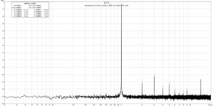
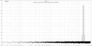
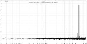
Here you can see some measurements of amanero cronus and b3se
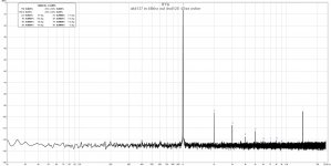
Photo 1 shows foobar upsampling to 384k and 1k
Photo 2 shows foobar sampling to 48k and 1k
Photo 3 shows foobar sampling to 48k and 13 & 14k
Photo 4 shows foobar sampling to 48k and 19 & 20k
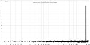
Photo 5 shows foobar upsampling to dsd128 and 1k
Here you can already notice that the 14khz artefact disappeared because of the isolator being used between amanero and cronus
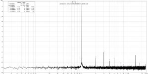
Photo 1 shows foobar upsampling to 384k and 1k
Photo 2 shows foobar sampling to 48k and 1k
Photo 3 shows foobar sampling to 48k and 13 & 14k
Photo 4 shows foobar sampling to 48k and 19 & 20k
Photo 5 shows foobar upsampling to dsd128 and 1k
Here you can already notice that the 14khz artefact disappeared because of the isolator being used between amanero and cronus
Attachments
-
 amanero cronus b3se osfoff 48k in 384k out.jpg142.3 KB · Views: 72
 -
 amanero cronus b3se osfon 48k in 48k out.jpg141 KB · Views: 72
 -
 amanero cronus b3se osfon 48k in 48k out 13k&14k.jpg132.7 KB · Views: 68
 -
 amanero cronus b3se osfon 48k in 48k out 19k&20k.jpg131.3 KB · Views: 55
 -
 amanero cronus b3se osfon 48k in dsd128 out.jpg142.3 KB · Views: 51
And now finally after being sure that the src board works as expected I decided to give it one more try and connect it again after cronus.
If I try to use the the divided clock from cronus for the src, same clock that goes also to amanero, I get wrong sample rate reading on the display of my dac. The dac has its own 100mhz clock.
For example I opted to upsample in foobar 44.1khz and multiples to 352.8khz and 48khz and multiples to 384khz.
If I choose that the src upsamples to 384khz and I play a 44.1khz file, foobar ouputs 352k and the src should output 384k but the controller of the dac shows 352khz.
Same happens if I play a 48k file, foobar upsamples it to 384 but if I choose that the src downsamples to 352k i will get 384khz on the display of my dac.
Please note that the sound is ok or at least seems ok.
I have to play more with this to get a better idea of what is happening.
Seeing that the issue from above happens I decided to solder back the ldo and the resistors on the src board and this way it will use its own clocks.
Well like this I could get correct readings from my dac for the pcm input sample rates.
There is also one small issue. If I play a 48k file, upsample it with foobar to 384k then send it to the src and choose to output 384k everything sounds fine.
Instead if I play a 384k file with foobar with no upsampling and send it to the src board that outputs it at 384k, I will get a distorted sound. I get same distorted sound even I convert to dsd in this case.
Else it`s working fine with files until 192k.
I didn`t manage to stream dsd files from foobar bacause I didn`t connect the dsdon pin from amanero so the src mcu doesn`t switch for dsd.
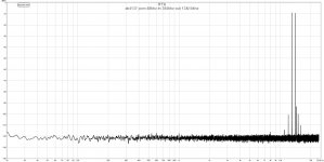
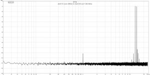
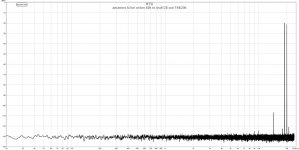
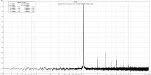
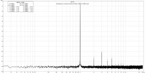
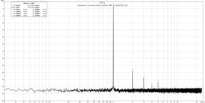
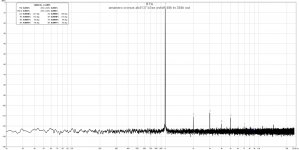
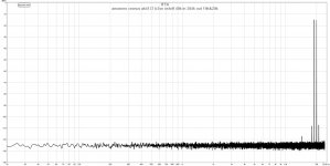
Like in the other configurations I have done some measurements also for this configuration.
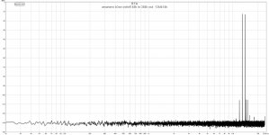
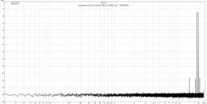
Photo 1 shows foobar sampling to 48k and ak4137 upsampling to 384k 1k
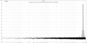
Photo 2 shows foobar sampling to 48k and ak4137 upsampling to 384k 13 & 14k
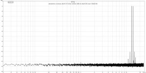
Photo 3 shows foobar sampling to 48k and ak4137 upsampling to 384k 19 & 20k
Photo 4 shows foobar sampling to 48k and ak4137 upsampling to dsd128 1k
Photo 5 shows foobar sampling to 48k and ak4137 upsampling to dsd128 13 & 14k
Photo 6 shows foobar sampling to 48k and ak4137 upsampling to dsd128 19 & 20k
If I try to use the the divided clock from cronus for the src, same clock that goes also to amanero, I get wrong sample rate reading on the display of my dac. The dac has its own 100mhz clock.
For example I opted to upsample in foobar 44.1khz and multiples to 352.8khz and 48khz and multiples to 384khz.
If I choose that the src upsamples to 384khz and I play a 44.1khz file, foobar ouputs 352k and the src should output 384k but the controller of the dac shows 352khz.
Same happens if I play a 48k file, foobar upsamples it to 384 but if I choose that the src downsamples to 352k i will get 384khz on the display of my dac.
Please note that the sound is ok or at least seems ok.
I have to play more with this to get a better idea of what is happening.
Seeing that the issue from above happens I decided to solder back the ldo and the resistors on the src board and this way it will use its own clocks.
Well like this I could get correct readings from my dac for the pcm input sample rates.
There is also one small issue. If I play a 48k file, upsample it with foobar to 384k then send it to the src and choose to output 384k everything sounds fine.
Instead if I play a 384k file with foobar with no upsampling and send it to the src board that outputs it at 384k, I will get a distorted sound. I get same distorted sound even I convert to dsd in this case.
Else it`s working fine with files until 192k.
I didn`t manage to stream dsd files from foobar bacause I didn`t connect the dsdon pin from amanero so the src mcu doesn`t switch for dsd.
Like in the other configurations I have done some measurements also for this configuration.
Photo 1 shows foobar sampling to 48k and ak4137 upsampling to 384k 1k
Photo 2 shows foobar sampling to 48k and ak4137 upsampling to 384k 13 & 14k
Photo 3 shows foobar sampling to 48k and ak4137 upsampling to 384k 19 & 20k
Photo 4 shows foobar sampling to 48k and ak4137 upsampling to dsd128 1k
Photo 5 shows foobar sampling to 48k and ak4137 upsampling to dsd128 13 & 14k
Photo 6 shows foobar sampling to 48k and ak4137 upsampling to dsd128 19 & 20k
Attachments
-
 amanero cronus ak4137 b3se osfoff 48k in 384k out.jpg142.5 KB · Views: 85
 -
 amanero cronus ak4137 b3se osfoff 48k in 384k out 13k&14k.jpg134.1 KB · Views: 68
 -
 amanero cronus ak4137 b3se osfoff 48k in 384k out 19k&20k.jpg133.2 KB · Views: 60
 -
 amanero cronus ak4137 b3se osfon 48k in dsd128 out 19k&20k.jpg132.7 KB · Views: 70
 -
 amanero cronus ak4137 b3se osfon 48k in dsd128 out 13k&14k.jpg134.3 KB · Views: 57
 -
 amanero cronus ak4137 b3se osfon 48k in dsd128 out.jpg141.3 KB · Views: 57
In post #1 you call it a "measurement artefact" but later you just say artefact. To me it seems like the isolator is doing som good and if so, it's not really a measurement problem..? Or?
//
I think it is something related to the ground connection...when I have the isolator in the circuit the spike is not present or maybe is present at a much lower level.
If I try to use the the divided clock from cronus for the src, same clock that goes also to amanero, I get wrong sample rate reading on the display of my dac. The dac has its own 100mhz clock.
For example I opted to upsample in foobar 44.1khz and multiples to 352.8khz and 48khz and multiples to 384khz.
If I choose that the src upsamples to 384khz and I play a 44.1khz file, foobar ouputs 352k and the src should output 384k but the controller of the dac shows 352khz.
Same happens if I play a 48k file, foobar upsamples it to 384 but if I choose that the src downsamples to 352k i will get 384khz on the display of my dac.
The way that sample rate displays work are based on what the firmware thinks is most likely.
For AK4137, displayed sample rates on it are based on which of its clocks it thinks it has selected and on what the target sample rate would be with that clock.
For Sabre dacs like B3, received sample rate is estimated from something called DPLL Number in the dac registers. It gives a ratio of the received sample rate compared to the dac clock (100MHz in this case) as divided by the internal Sabre master clock divider, if used. Most MCU algorithms assume only standard audio sample rates will be received so they take a range of DPLL numbers and associate that with the closest standard sample rate.
In other words, don't believe any of the displayed sample rates if you are playing around with non-standard clocks and sample rates. The dac and AK4137 should still work fine, just so long as their maximum clock rates are not exceeded. 100MHz is fine for a Sabre dac, and I have used 25Mhz to clock AK4137 without any problems.
If I play a 48k file, upsample it with foobar to 384k then send it to the src and choose to output 384k everything sounds fine.
Instead if I play a 384k file with foobar with no upsampling and send it to the src board that outputs it at 384k, I will get a distorted sound. I get same distorted sound even I convert to dsd in this case.
Else it`s working fine with files until 192k.
I didn`t manage to stream dsd files from foobar bacause I didn`t connect the dsdon pin from amanero so the src mcu doesn`t switch for dsd.
Regarding troubleshooting of the distortion/no-distortion issue, you might want to take a look at all the AK4137 input settings and make sure they are matched to what it is actually receiving. For example, LJ and I2S settings can both seem to work but one will distort when fed full level signals of the other.
Another thing to check is actual BCLK and LRCK frequencies going into the AK4137 board using a scope. That will tell what the actual bit depth and sample rate are.
My ak4137 selects by itself the type of input between i2s and dsd.
I can set it up to output i2s/dsd or right justified(I suppose). The input of my dac is set to i2s and the ouput of the src the same to i2s.
Just for curiosity I setup the src to output right justified and set also the dac to accept rj. The sittuation is the same as first.
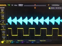
Seen the above sittuation I decided to pull out the scope and check BCLK and LRCK signals.
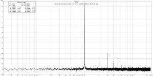
Image 1 and 2 show a 192k file played from foobar at 192k. The measurements were taken at cronus output.
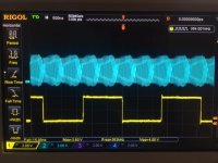
Image 3 and 4 show a 384k file played from foobar at 384k. The measurements were taken at cronus output.
Image 5 and 6 show a 48k file played from foobar and upsampled(in foobar) to 384k. The measurements were taken at cronus output.
Attachments
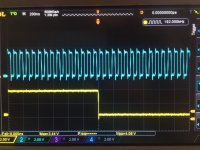
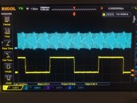
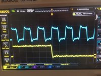
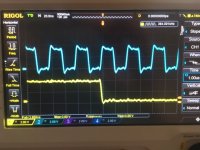
Looks like too much aliasing on the blue BCLK signal in some of the images, not useful to see that.
Also, don't know what features your scope has but kind of looks like there is a separate frequency counter on channel 1 (yellow) that displays even if one cycle is not present on the scope display. In addition to that it looks like the scope typical measurement function that displays below the waveforms is set to display some parameters of channel 1 including frequency. That frequency display only works when at least one cycle of the waveform is present on the display.
Given the above described appearances, can you set the scope to trigger from channel 1 with high enough sweep speed to show a stable BCLK display showing at least one cycle, and set the measurement function to display channel 2 frequency? If so, maybe we can read out both clock frequencies at the same time while looking at unaliased stable waveforms. Something like that, your choice
In addition, not sure what bandwidth your scope has but BCLK rise times look slow, and there is a lot of ringing on top of the waveform. Clock wires too long, lack of buffering, and lack of a series resistor at the buffer output all contribute to degraded clock signal. Maybe interesting/useful to see what BCLK waveform looks like in single sweep mode and in averaged acquisition mode too.
While waveform is not good, it probably has nothing to do with distortion or not. Regarding distortion, does the problem only happen if AK4137 is in the signal path?
I have seen strong distortion from mismatched word-length and or LJ/I2S/RJ settings. I have seen a more subtle distortion if Sabre dac doesn't like the jitter profile of the AK4137 clock (assuming the distortion is related to AK4137 at all).
A smaller yet distortion can arise from intersample overs. If using Windows to drive Amanero, the usual precautions should be taken to make sure Windows Sound Engine is not messing with the output of Foobar with ASIO component (Foobar ASIO driver, Windows volume for Amanero full up, Amanero not set to Windows default comms device nor default sound device). In addition, probably wise to turn down Foobar digital output by 3dB or more to check for any level sensitivity of distortion.
EDIT: Estimating from scope display, at 384kHz sample rate BCLK ~25MHz which implies 32-bit word size. 384x10^3 x 2-channels x 32-bits = 24.576x10^6 Hz
Presumably, AK4137 is also set for 32-bit input and output word sizes. Please confirm.
Last edited:
Yes, the problem is only when I insert ak4137 in the chain. To be more clear the issue appears only on the loud passages of the track(only on 384/352k tracks) and seems more like it’s clipping the signal.
I am sure the problem is not from my pc since it happens only when ak4137 is in the chain.
I have tried also to lower the output from foobar but with no luck. I will give it a try again.
I have taken a photo as you requested but if I upload it from my phone it will be uploaded flipped, don’t know why this happens all the time... I will upload it later when I get back to my pc.
If it happens on the loud passages that suggests there could be a mismatch in protocols which will happen if AK4137 is set to LJ input when Amanero is outputting I2S (IIRC). Try setting AK4137 input to whichever gives the lowest output volume I2S input or LJ.
Presumably a similar kind of thing could happen if AK4137 output was set for I2S and dac chip is set for LJ input (again, IIRC about the order when it happens).
Otherwise, it could be that the upsampling filter used in Foobar is raising the output level too much. You could experiment with turning Foobar output volume slider down to see if distortion can be changed/stopped by doing that. If so, how much attenuation does it take?
Also, it might make sense to see if a similar problem happens at other sample rates or if it is unique to 384kHz. Generally speaking, its usually be use to use AK4137 to upsample, unless perhaps using to convert to DSD256 (in which case upsampling at the same time would probably reduce sound quality).
Offhand, I can't think of a reason AK4137 should distort with an input level that doesn't make the dac chip distort when AK4137 is removed from the circuit. Heavy distortion on loud passages suggests mismatched LJ/I2S protocols somewhere.
Light distortion could indicate progressively increasing intersample overs as resampling filters at each stage increase the output level a bit. There can be resampling filtering in Foobar, in AK4137, and in ES9028PRO ASRC stage (not to mention later oversampling).
If the issue only happens in the case of 384kHz input to AK4137 and 384kHz output from AK4137 at the same time, I probably wouldn't worry too much if the cause cannot be found. If you have a fast logic analyzer such as a Salae that can keep up with 384kHz I2S then you could probably measure everything that is going on. Othewise, don't worry too much since it probably doesn't make too much sense to want to resample 384kHz to 384kHz using AK4137 except maybe under rather unusual dual clock domain circumstances, something that should't be necessary if using Cronus.
AK4137 is probably best used to convert incoming 192kHz or 176kHz to DSD256. That's where it should probably make the most improvement in ES9028 sound quality. In addition, chances of getting ES9028PRO to run in sync mode or at least with a very low DPLL bandwidth are probably better if AK4137 is running from a low jitter divided dac clock. Possibly, reclocking AK4137 output through a D-flip flop would help with that. Another thing that would probably help would be to run AK4137 in its input A/B I2S source selector IC from a separate low noise voltage regulator attached to the back side of the AK4137 PCB (the ground plane side). A good choice might be: TPS7A4700 Ultra Low Noise Adjustable Voltage Regulator 1.4V-20V 1A Power Supply 699942464591 | eBay
Last edited:
...One last thing to bear in mind is that by default AKM runs its DSD clock phase inverted from most of the rest of the world. That can be changed in AK4137 I2C registers. A hardware fix to try might be to run BCLK through an inverter IC when using AK4137 for converting to DSD. With the inverted clock, ES9028PRO will still play sound, but sound quality may be mixed given that DSD data will be changing when the dac chip expects it to be stable. Don't recall offhand if the dac chip has a register setting to handle an inverted DSD clock, don't remember one.
Last edited:
I don’t have any settings for ak4137 input. I think it’s default i2s.
When I play the 384k file I use no upsampling in foobar.
If for example I play a 48k file and upsample it in foobar to 384k and then send it to the ak4137 I don’t have that issue.
The issue happens only when I stream 352/384k files.
So if I play a 352/384k file and set ak4137 to ouput it as pcm 384 or dsd128 I get that clipped sound.
My dac is es9018 which runs async(100mhz clock) and it goes well until dsd128.
My dac is es9018 which runs async(100mhz clock) and it goes well until dsd128.
Ouch! ES9018 was not ESS's best work. Don't know of any reason why it should not be able to play DSD256. BCLK is ~11MHz. The only requirement I see is that MCLK must be greater than 3fs, which would be greater than ~33MHz. Since you are using 100MHz clock, should't be a problem even for DSD512.
However, if you are using DoP that cuts sample rate in half. Should be no reason to do that between AK4137 output and dac chip input.
Last edited:
AK4137 Datasheet says the default PCM input format is 32-bit MSB justified, which I assume means LJ. However, the AK4137 board's MCU may set it to I2S mode in I2C register 0x01. You could take a peek with a $10 logic analyzer from Amazon or from ebay. They are fast enough for I2C but not for I2S. Amazon.com: HiLetgo USB Logic Analyzer Device With EMI Ferrite Ring USB Cable 24MHz 8CH 24MHz 8 Channel UART IIC SPI Debug: Clothing
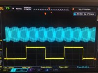
Why do you have channel 2 (blue) up while aliased? Are you used to setting up the scope for different applications? What model scope is it?
DSD produces noise, could be insufficient filtering in your output stage when running DSD256. Something that should probably be tracked down to find the cause and correct it.
DSD produces noise, could be insufficient filtering in your output stage when running DSD256. Something that should probably be tracked down to find the cause and correct it.
Last edited:
I gave a try to your advice of lowering the volume from foobar, well guess what, starting with -3db things started to improve a lot but I can still hear the clipping very soft this time on some trumpets. At -5db problem is solved, there is no more any sign of clipping and the trumpets sing at their best
Thnaks.
Thnaks.
Why do you have channel 2 (blue) up while aliased? Are you used to setting up the scope for different applications? What model scope is it?
DSD produces noise, could be insufficient filtering in your output stage. Something that should probably be tracked down to find the cause and correct it.
I moved on channel up and the other down for better visibility. I can change to have them both one over the other.
The last time I used the scope I monitored some uart data lines.
The scope is a Rigol DS1054Z.
As you can see I`m not an expert in using it but I try to do my best.
- Status
- This old topic is closed. If you want to reopen this topic, contact a moderator using the "Report Post" button.
- Home
- Source & Line
- Digital Line Level
- Interfacing Amanero, Cronus and AK4137