I was inspired by a thread I read here on diyaudio back in November about current production 7591A tubes by New Sensor and JJ. I’d known about the 7591A, but I hadn’t played with it before, and I hadn’t known that it had been reintroduced by two different manufacturers. I designed a circuit board for a very simple stereo amplifier and built a prototype. It turned out better than I expected, so I thought I’d share it.
I really like this little tube!! It seems that Westinghouse was telling the truth about its linearity.
I spent a few days with a THD analyzer optimizing component values, and especially exploring the operating point for the 7591A push-pull output stage. I’m getting about 35W per channel with both channels driven, and quite respectable THD readings. The Tung Sol Reissue 7591A works well, and I have a set of JJ 7591S that I intend to try as well. The JJ 7591S in particular seems reasonably priced, at least in the US.
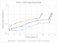
I had originally intended to use ultra-linear (UL) operation, but I found that the 7591A seems to work much better as a pentode (see the THD readings: "proto_meas.pdf"). And when I added a 390v screen regulator, I was very pleased to see the improvement in THD. THD at 1kHz is below 0.1% up to 25W, and only 0.15% at 35W. Note that the THD data was taken with a 5-ohm load on the 4-ohm tap of a Triode A-470 output transformer, which yields an effective 5400-ohm plate-to-plate load. Power output and distortion are almost the same with a 6500-ohm plate-to-plate load.
The amp sounds quite nice when driving my Maggies, even with its modest output power. The next step for me is to revise the circuit board design, to include the screen regulator on the PCB. And then build it into a box. The PCB is only 10” x 6”, so the final amp will be quite compact, limited by the size of the transformers.
But first, I was curious if anyone in the diyaudio community has insight into the 7591A’s strong preference for operating in pentode mode, especially with the regulated screen supply?? Looking through the schematics of classic equipment from the 1960s, I don’t find any using the 7591A in UL mode. I did see a post from a couple years back using the 7591 with cathode feedback, but without any measured data. If there’s anything I can do to improve the linearity even further, it’s best to do it now, before I redesign the PCB…….
If there is interest, I’d be happy to post the revised schematics when the new PCB is done. New amp designs using these reintroduced 7591 tubes seem relatively rare, but I think they deserve more attention.
I really like this little tube!! It seems that Westinghouse was telling the truth about its linearity.
I spent a few days with a THD analyzer optimizing component values, and especially exploring the operating point for the 7591A push-pull output stage. I’m getting about 35W per channel with both channels driven, and quite respectable THD readings. The Tung Sol Reissue 7591A works well, and I have a set of JJ 7591S that I intend to try as well. The JJ 7591S in particular seems reasonably priced, at least in the US.
I had originally intended to use ultra-linear (UL) operation, but I found that the 7591A seems to work much better as a pentode (see the THD readings: "proto_meas.pdf"). And when I added a 390v screen regulator, I was very pleased to see the improvement in THD. THD at 1kHz is below 0.1% up to 25W, and only 0.15% at 35W. Note that the THD data was taken with a 5-ohm load on the 4-ohm tap of a Triode A-470 output transformer, which yields an effective 5400-ohm plate-to-plate load. Power output and distortion are almost the same with a 6500-ohm plate-to-plate load.
The amp sounds quite nice when driving my Maggies, even with its modest output power. The next step for me is to revise the circuit board design, to include the screen regulator on the PCB. And then build it into a box. The PCB is only 10” x 6”, so the final amp will be quite compact, limited by the size of the transformers.
But first, I was curious if anyone in the diyaudio community has insight into the 7591A’s strong preference for operating in pentode mode, especially with the regulated screen supply?? Looking through the schematics of classic equipment from the 1960s, I don’t find any using the 7591A in UL mode. I did see a post from a couple years back using the 7591 with cathode feedback, but without any measured data. If there’s anything I can do to improve the linearity even further, it’s best to do it now, before I redesign the PCB…….
If there is interest, I’d be happy to post the revised schematics when the new PCB is done. New amp designs using these reintroduced 7591 tubes seem relatively rare, but I think they deserve more attention.
Attachments
I have some "tidbits" for you to mull over.
The 7591 is easy to drive, a fact that Fisher, Scott, Sherwood ... took full advantage of. Small signal circuitry that works with "12" W. tubes, like the 6BQ5, also works with the 7591. Your Mullard style setup may have too much small signal gain.
Current production 7591s are intolerant of liberties being taken with the grid to ground resistance limit specification. FWIW, my method for "finessing" that issue is employing combination bias. "Stand" a PP pair on a shared 100 Ω/47 μF. bias network. A single bias trim pot. suffices for the pair. Notice the convenient bias set test point. Matching requirements are reasonably relaxed. As is always the case, gm numbers must be close, but some variance in cathode current numbers is OK.
Search the archives here and over on AA for "El Cheapo Grande".
Your findings about UL vs. full pentode are interesting. Perhaps employing (costly ) separate screen grid winding O/P "iron" would yield yet better results. UL combined with regulated g2 B+ has been previously shown to be advantageous. Another, less expensive, possibility is "iron" whose UL taps are at approx. 20%. Edcor has at least 1 23% model. Maybe Edcor would wind 6.6 Kohm primaries with the UL taps at approx. 20%.
The 7591 is easy to drive, a fact that Fisher, Scott, Sherwood ... took full advantage of. Small signal circuitry that works with "12" W. tubes, like the 6BQ5, also works with the 7591. Your Mullard style setup may have too much small signal gain.
Current production 7591s are intolerant of liberties being taken with the grid to ground resistance limit specification. FWIW, my method for "finessing" that issue is employing combination bias. "Stand" a PP pair on a shared 100 Ω/47 μF. bias network. A single bias trim pot. suffices for the pair. Notice the convenient bias set test point. Matching requirements are reasonably relaxed. As is always the case, gm numbers must be close, but some variance in cathode current numbers is OK.
Search the archives here and over on AA for "El Cheapo Grande".
Your findings about UL vs. full pentode are interesting. Perhaps employing (costly
) separate screen grid winding O/P "iron" would yield yet better results. UL combined with regulated g2 B+ has been previously shown to be advantageous. Another, less expensive, possibility is "iron" whose UL taps are at approx. 20%. Edcor has at least 1 23% model. Maybe Edcor would wind 6.6 Kohm primaries with the UL taps at approx. 20%.I believe the driving force for the 7591A was to create a tube that would fit in the receiver form factor and allow for a "100W" output power rating. To get there, pentode operation sure helps and the Westinghouse datasheet provides some UL operating points that support this.
I still need to bench test my 1000A to verify the 100W claim. I suspect it's close, but not close enough!
Let us know what you think of UL, you may be one of the only people alive to evaluate 7591As in UL.
I still need to bench test my 1000A to verify the 100W claim. I suspect it's close, but not close enough!
Let us know what you think of UL, you may be one of the only people alive to evaluate 7591As in UL.
Looks like a nice amp! Your topology is exactly what I have been thinking about for the past few weeks, though I was thinking 6L6's. I just bought a pair of 8k 40W output transformers for a stereo amp project. Can you talk about your CCS and where is VCC going?
I have a pair of IXCP 10M90S - can those be used?
I have a pair of IXCP 10M90S - can those be used?
I have an amp with 7591's. Was initially in triode mode but power was too limited so I changed to pentode with screen regulation. I don't have ultralinear taps on the output transformer so can't try that. I initially had JJ's installed but one went bad after about 4 years and I replaced all four with EH's. Power output increased, I think the "knee" on the JJ's is at a higher voltage so I was getting reduced maximum voltage swing.
For your design (which looks great) you might want to rearrange the bias circuitry as with the current arrangement if the pot wiper loses contact you lose bias voltage. Other arrangements can drive the grids to full negative voltage if the wiper loses contact.
For your design (which looks great) you might want to rearrange the bias circuitry as with the current arrangement if the pot wiper loses contact you lose bias voltage. Other arrangements can drive the grids to full negative voltage if the wiper loses contact.
Looks like a nice amp! Your topology is exactly what I have been thinking about for the past few weeks, though I was thinking 6L6's. I just bought a pair of 8k 40W output transformers for a stereo amp project. Can you talk about your CCS and where is VCC going?
I have a pair of IXCP 10M90S - can those be used?
OntarioMaximus,
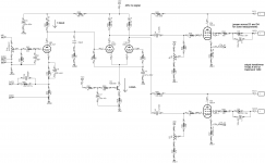
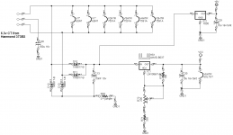
Vcc is a 6.3v DC regulated supply for the 6SL7GT heater. I posted the schematic below. Your IXCP 10M90S should make a fine current source, but you'll have to use a different circuit than I did. My circuit is just the classic bipolar transistor constant current source, which works well here.
Everyone,
Thanks for your comments! I re-posted the THD measurements as a png file, so they're easier to look at. So far, I've drawn two conclusions:
1. UL operation doesn't seem to be a good choice for the 7591A. If you look at distortion at moderate levels around 12W, THD in UL mode is almost 8 times higher than it is with a regulated screen supply.
2. The 7591A is an exceptionally linear tube. You'd have to work pretty hard with any other common beam power tube to get distortion as low as the 7591A gives with just this simple circuit. I think the Westinghouse engineers did a good job back in 1960. And I think the Tung Sol Reissue 7591A is a very good copy of the original. I have the Westinghouse 1963 data sheet, if anyone would like me to post it.
I plan to measure THD with the JJ 7591S this weekend, and I'll post the results.
Scott
Attachments
I measured the performance of all three current production 7591 types in my prototype, including the Tung Sol Reissue 7591A (which I used originally), the JJ 7591S, and the Electro-harmonix 7591A. They were all measured with the 390v regulated screen supply, 30mA bias current, and a plate supply that varied from 450v at no signal down to 410v all full output for both channels. They all work reasonably well, but I was a bit disappointed in both the JJ and EH tubes, for different reasons.
The JJ 7591S has lower power output than the other types, 30W vs. 37W for the Tung Sol Reissue, and the JJ screens glow bright orange when operated continuously at full power. The JJ 7591S would not be a good choice for a guitar-amp, that's for sure. I've had good luck with other JJ types (such as the 2A3-40), but not so much here. I think maybe the 7591"S" means "sort-of". It sounds just fine, however.
The EH 7591A produces nearly as much power (34W) as the Tung Sol Reissue, but the THD plot conceals a few problems. The four EH 7591A samples I have produce high levels of 5th order harmonics even well below clipping. And the EH 7591A clipping characteristic is ugly. In contrast, both the Tung Sol Reissue and JJ produce mainly 3rd and 2nd order distortion, and the clipping is soft and rounded. Unfortunately, I measured the EH 7591A before listening to it, so I was prejudiced against it, but I didn't like the sound at all. Maybe others have better experiences?
So I still really like the Tung Sol Reissue 7591A, but the others less. I hope this data is useful for other 7591A users.
I plan one more experiment - I've created a version of my PCB that accepts 6L6GC and EL34, and I'll compare their linearity and power output with these 7591A under similar conditions. Anyone out there want to predict what I'll find?
Scott
Attachments

That is a very nice amplifier project.
I hope you always have Super 5AR4 tubes.
5AR4 specs:
60uF max first cap, you have 82 uF
At 350VAC, you need 100 Ohms series resistance (does the center tap to 1/2 primary have that much resistance? If not, use a 100 Ohm resistor in each plate lead, or higher wattage 100 Ohm resistor in the cathode lead (Of course if you already have 50 Ohms 1/2 primary DCR, then use 50 Ohm resistors, etc.
I once made the mistake of using a 100uF first cap, and the rectifier arced over.
I learned my lesson.
If you have trouble in the future, remember you have 82uF, and an unknown series resistance in the plates / cathode circuits.
Last edited:
That is a very nice amplifier project.
I hope you always have Super 5AR4 tubes.
5AR4 specs:
60uF max first cap, you have 82 uF
At 350VAC, you need 100 Ohms series resistance (does the center tap to 1/2 primary have that much resistance? If not, use a 100 Ohm resistor in each plate lead, or higher wattage 100 Ohm resistor in the cathode lead (Of course if you already have 50 Ohms 1/2 primary DCR, then use 50 Ohm resistors, etc.
I once made the mistake of using a 100uF first cap, and the rectifier arced over.
I learned my lesson.
If you have trouble in the future, remember you have 82uF, and an unknown series resistance in the plates / cathode circuits.
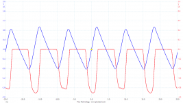
Yes, thanks, that's a good thing to check. It's straightforward to measure the peak current in a rectifier, by temporarily using a 1 ohm resistor between the CT of the high voltage winding and ground. I plotted the voltage across this 1 ohm resistor in red. And in blue is the divided-by-ten ripple voltage across the first 82uF capacitor. At maximum signal in both channels, the peak current is about 900mA, versus the 825mA rating of the 5AR4. Peak-to-peak ripple is about 17V. But at no signal, the peak current is about 450-500mA, well within the 5AR4 ratings.
So if the amplifier were run continuously at full power, the 5AR4 may have a shortened life, but HiFi amps only reach full power during brief peaks, if ever. So I'm thinking all is well, especially since the HV secondary is fused. If it were for a guitar amp, I'd probably use 2 5AR4 in parallel, or perhaps a 5U4GB (with a 1A peak current rating), or use a smaller cap.
Scott
Attachments
TavishDad,
Do not forget to test for what happens in a Hot-Start condition.
The amp is warm.
The power mains goes off temporarily.
The B+ collapses to near zero, but all the filaments and cathodes are still hot.
Now the power mains come on, and that Is the max current, caps at zero volts, but filaments and cathodes still hot.
Just sayin'
Lots of commercial amps don't tolerate that well and will pop a fuse.TavishDad,
Do not forget to test for what happens in a Hot-Start condition.
The amp is warm.
The power mains goes off temporarily.
The B+ collapses to near zero, but all the filaments and cathodes are still hot.
Now the power mains come on, and that Is the max current, caps at zero volts, but filaments and cathodes still hot.
I use solid state rectifier diodes for B+.
Turn-on Inrush current is from charging the capacitor, and from filaments that are low resistance when cold.
Hot-Start is a little different. The filaments are warm, so the filament current is normal.
But the rectifiers have to 1. charge the cap, and 2. power the hot tubes.
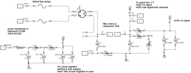
I use 2 fuses in series.
One fuse is a fast blow. It is just large enough to take care of current transients during both amp turn-on, and during Hot Starts.
The other fuse is a slow blow (lower amp rating than the fast blow). It takes care of the operating current of the amplifier, both quiescent, and with large signal applied.
Turn-on Inrush current is from charging the capacitor, and from filaments that are low resistance when cold.
Hot-Start is a little different. The filaments are warm, so the filament current is normal.
But the rectifiers have to 1. charge the cap, and 2. power the hot tubes.
I use 2 fuses in series.
One fuse is a fast blow. It is just large enough to take care of current transients during both amp turn-on, and during Hot Starts.
The other fuse is a slow blow (lower amp rating than the fast blow). It takes care of the operating current of the amplifier, both quiescent, and with large signal applied.
Eli Duttman,
I have been going through the postings on this thread again.
You suggested possibly using a 7591 in Ultra Linear mode with 20% to 23% UL tap.
Well, all other things being equal, that is harder on the 7591 than a 40% UL tap.
The screen voltage is higher than the plate voltage because the drop below B+ is about 20% of the DCR, times the sum of the plate and screen currents.
But the plate voltage drop is about 100% of the DCR times the plate current (Ok then, plus 20% of the DCR times the screen current).
So we are starting with more screen voltage at a 20% tap, than what the screen voltage would be at a 40% tap.
And then we apply signal . . .
1. Lets suppose the plate swings downward 300V. At a 20% tap, the screen only goes down by 0.2 x 300V = 60V. In that case, the plate went down 240V more than the screen (the screen voltage that was already higher than the quiescent plate volts).
2. Lets suppose the plate swings downward 300V. At a 40% tap, the screen goes down by 0.4 x 300V = 120V. In that case, the plate only went down 180V more than the screen (the screen voltage that was already higher than the quiescent plate volts).
3. Pick your max screen current with signal applied. A lot more in # 1. than in # 2.
4. As the UL tap number of % goes up, a limit is reached . . . Triode wired mode, and the plate voltage and screen voltage are always equal, quiescent, and with signal applied.
Last edited:
- Home
- Amplifiers
- Tubes / Valves
- New 7591A Amp Design, 35W x2