Hey All
After about a week of listening to my new SSE amp I figured I would share my checkout and updates on the amp.
First off I am very pleased with the overall sound of the amp and the ease of the build, minus my errors I made while assembling the chassis and selecting some of the components. Best advice I can give is to double check all the values of caps, resistors and your wiring! As many of you know as long as you stick to the build guide George has provided you can have yourself a very nice tube amp.
Right now I am running the amp through a crappy bluetooth adapter as that is all is available to me at the moment. I plan on running this through my turntable with a phono pre yet to be determined.
I am listening to this through Klipsch RB 61 II bookshelf speakers, Klipsch is known for their highs/horns, so you can imagine I have plenty of highs. Only thing that is lacking just a little is the bass but these speakers arent bass beasts so i cant say its the amp. I have played some songs with deep bass and I do get a little kick but thats all these little bookshelf speakers will give me. Id like to audition the amp on different speakers but those are about all I have at the moment, plus I know I am losing sound quality from the bluetooth adapter, bluetooth was really never meant for audio signals.
Currently I am waiting to install my permanent RCA plugs and wire in my real Alps when it arrives and get rid the 100k pho alps I got off Ebay.
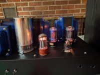
I have about 15hrs of listening time in and noticed last night after about an hr of play the amp was getting hot, pretty normal. I usually place a fan blowing across the tubes, excess heat is never a good thing. I noticed my tubes had a nice blue glow as you can see in the picture. Then I noticed my Tung Sol 6L6 on the left was glowing a little red in the plate. Time to take some measurements. I did notice the tip would normally glow a little more red than the next one but figured it was seeing a little more DC.
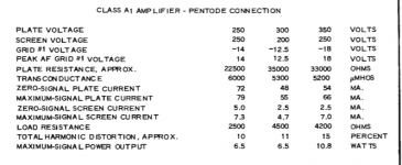
Here are my measurements as followed in this thread:
Simple SE checkout for dummies
This is what I am running iron wise:
XPWR035 trans, CXSE25-8-5k output transformers and a CXC125-10-200ma chokeR4/150 ohm-
B+ 475/474 VDC
R10/ 220 ohm 2.1 VDC 20mw, 9.5ma
R17/560 ohm 41.5 VDC 3.07 watts, 74ma
R20/220 ohm 2.1 VDC
R27/560 ohm 41.6 VDC 74.2ma 3.09w
Total dissipation R17/27 roughly 32 watts
All measurements taken with tubes in volume all the way open and amp warmed up for 30min
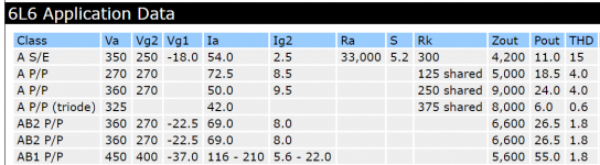
Does all this seem correct? If I am looking at the Data sheets right for the Tung Sol 6l6 I shoud be within range? Leave everything as is or try to put a resister in with R17 to get around 800ohms?
Maybe try some Kt88s, I was reading a thread last night about the unreliability of the 6l6, any input is appreciated!
After about a week of listening to my new SSE amp I figured I would share my checkout and updates on the amp.
First off I am very pleased with the overall sound of the amp and the ease of the build, minus my errors I made while assembling the chassis and selecting some of the components. Best advice I can give is to double check all the values of caps, resistors and your wiring! As many of you know as long as you stick to the build guide George has provided you can have yourself a very nice tube amp.
Right now I am running the amp through a crappy bluetooth adapter as that is all is available to me at the moment. I plan on running this through my turntable with a phono pre yet to be determined.
I am listening to this through Klipsch RB 61 II bookshelf speakers, Klipsch is known for their highs/horns, so you can imagine I have plenty of highs. Only thing that is lacking just a little is the bass but these speakers arent bass beasts so i cant say its the amp. I have played some songs with deep bass and I do get a little kick but thats all these little bookshelf speakers will give me. Id like to audition the amp on different speakers but those are about all I have at the moment, plus I know I am losing sound quality from the bluetooth adapter, bluetooth was really never meant for audio signals.
Currently I am waiting to install my permanent RCA plugs and wire in my real Alps when it arrives and get rid the 100k pho alps I got off Ebay.
I have about 15hrs of listening time in and noticed last night after about an hr of play the amp was getting hot, pretty normal. I usually place a fan blowing across the tubes, excess heat is never a good thing. I noticed my tubes had a nice blue glow as you can see in the picture. Then I noticed my Tung Sol 6L6 on the left was glowing a little red in the plate. Time to take some measurements. I did notice the tip would normally glow a little more red than the next one but figured it was seeing a little more DC.
Here are my measurements as followed in this thread:
Simple SE checkout for dummies
This is what I am running iron wise:
XPWR035 trans, CXSE25-8-5k output transformers and a CXC125-10-200ma chokeR4/150 ohm-
B+ 475/474 VDC
R10/ 220 ohm 2.1 VDC 20mw, 9.5ma
R17/560 ohm 41.5 VDC 3.07 watts, 74ma
R20/220 ohm 2.1 VDC
R27/560 ohm 41.6 VDC 74.2ma 3.09w
Total dissipation R17/27 roughly 32 watts
All measurements taken with tubes in volume all the way open and amp warmed up for 30min
Does all this seem correct? If I am looking at the Data sheets right for the Tung Sol 6l6 I shoud be within range? Leave everything as is or try to put a resister in with R17 to get around 800ohms?
Maybe try some Kt88s, I was reading a thread last night about the unreliability of the 6l6, any input is appreciated!
Attachments
Last edited:
I've been reading Morgan Jones' book "Building Valve Amplifiers" and one thing he goes into great detail on is proximity of tubes to each other and to other components. He also discusses convective air flow and "dead zones" (I think he calls them that).
Basically, it looks to me like you have sort of a perfect storm set up for that 6L6 to a) not release its own convective heat due to lack of local "chimney effect" and b) absorb radiant heat from nearby tubes and components. Also, the "global" chimney effect is pulling convective heat from the other tubes and components to the centre of the chassis, right where that tube is.
The other 6L6 is closer to the edge of the chassis (better convection) and further from other hot components (less secondary radiant heat) therefore it is cooler.
Your tests show that there is no electrical reason for one power tube to be considerably hotter.
But I am a newbie and I fully expect a more experienced person to tell me I am off base.")
Basically, it looks to me like you have sort of a perfect storm set up for that 6L6 to a) not release its own convective heat due to lack of local "chimney effect" and b) absorb radiant heat from nearby tubes and components. Also, the "global" chimney effect is pulling convective heat from the other tubes and components to the centre of the chassis, right where that tube is.
The other 6L6 is closer to the edge of the chassis (better convection) and further from other hot components (less secondary radiant heat) therefore it is cooler.
Your tests show that there is no electrical reason for one power tube to be considerably hotter.
But I am a newbie and I fully expect a more experienced person to tell me I am off base.
Last edited:
By the way - if I am correct, the simplest solution would be to create a perforated area (drill some holes) all around the base of that tube socket so that convective air currents can draw cooler air from inside the chassis, up over the tube. This also creates air flow through the components inside the chassis itself. Probably best to remove the board from the chassis first.
Again, this is all sourced from Mr. Jones' wisdom, and it sure as heck makes sense to me.
Again, this is all sourced from Mr. Jones' wisdom, and it sure as heck makes sense to me.
By the way - if I am correct, the simplest solution would be to create a perforated area (drill some holes) all around the base of that tube socket so that convective air currents can draw cooler air from inside the chassis, up over the tube. This also creates air flow through the components inside the chassis itself. Probably best to remove the board from the chassis first.
Again, this is all sourced from Mr. Jones' wisdom, and it sure as heck makes sense to me.
Thanks for the input I have been looking up some small fans I can install in the chassis as you have mentioned. I'll also have to cut some holes in my bottom plate and install some screens.
All that does make sense, as I mentioned I placed a window fan between the two speakers and had a pretty good flow of air. I just played the amp for over an hour and no red plate.
Lots of ways to skin that cat!
For me, fans are a last resort simply because I don't want the noise. Having said that, I have a EL34 push-pull amp and its power transformer gets way hotter than it should, so I cut down a CPU heatsink to size and zip-tied it onto the back of the tranny (with some heat-sink compound), then installed a small CPU fan on it. It works great, but as I said - I don't like the sound (even though it is fairly quiet).
I got about 32 watts PD per power tube, which, if my arithmetic is correct, will lead to a very short tube life for 6L6GC. This out of spec power is the reason one tube is showing red in the plate structure. In a dim room, you might see red in the plate of the other tube. IIRC, 30 watts is the maximum spec for 6L6GC, and 7581/KT66 is 35 watts.
21 to 25 watts would lead to a longer tube life. You might want to consider trying a 620 to 680 ohm cathode resistor.
I think your amp looks good; I can't see any reason why you would need a fan to cool the tubes or other parts. Vacuum tube stuff is made to run hot, and does - often for decades without any component or tube failures. If you have an IR thermometer you can measure temps and see if they are within the specification for your parts, but unless you have a real reason to worry about it, I would not.
If you happen to have a 5U4 rectifier you could pop that in and it will drop your B+ considerably. Maybe enough to bring the 6L6 plate dissipation down a few watts. I am not saying this is a better solution than increasing cathode resistor value (that's for sure) - but convenient if you have one handy.
Isn't the problem with B+?
Va is 434V (475 - 41) - shouldn't it be around 350V?
Aren't talking about plate voltage here?
https://frank.pocnet.net/sheets/127/6/6L6GC.pdf
Says max is 450v.
Yes, but not Class A ...
That's for pentode mode. Are the ratings different for triode connected? I'm not trying to be a PITA, just trying to learn.
If you are correct, it means George has designed an amp that runs the 6L6 WAY beyond spec, which I find hard to believe.
Note: I see now that the data sheet I posted states 250v (typical) for triode as well.
Interesting...
On the other hand, the Russian 6P3S-E (approximate 6L6 equivalent) is officially a 250v unit and lots of people run them reliably at 400-450v.
Last edited:
I am fairly new to this game, so I am just going on what I have absorbed the last couple of years.
Here is the 'Tubes and Applications page for the SSE:
Tubes and applications
B+ is mentioned there as being 375V. Then again, there are simulations at higher voltages on that page, so maybe I have misunderstood ;-) Mine is around 407V, and I have EL34's that cope with that OK.
Here is the 'Tubes and Applications page for the SSE:
Tubes and applications
B+ is mentioned there as being 375V. Then again, there are simulations at higher voltages on that page, so maybe I have misunderstood ;-) Mine is around 407V, and I have EL34's that cope with that OK.
430 volts across the new Tung Sol 6L6GC is fine. I have run over 500 volts across that tube without breakdown.
Right now, OP's tubes are running excessive power, and it needs to be reduced to a more reasonable level. This can be done by decreasng the voltage across the tube, decreasing the current through the tube, or a combination of both. Generally, more voltage increases power output, more current decreases distortion, either effect may or may not be audible, so some experimentation ( fun ) could be worthwhile.
Different rectifier tubes have different voltage drops and can change the voltage at the tubes. One should make sure the power transformer 5 volt winding is adequate as some rectifer tubes ( 5U4 ) draw 3 amps. 5T4 is essentially a metal 5U4, but draws only 2 amps from the 5 volt line.
There are at least two types of Russian 6P3S. I would not put 450 volts across either one, and they are not 30 watt tubes.
Last edited:
Isn't the problem with B+?…… George has designed an amp that runs the 6L6 WAY beyond spec, which I find hard to believe...… lots of people run them reliably at 400-450v.
Plate or tube VOLTAGE is not the problem, but excess dissipation caused by the higher than expected B+ voltage IS a BIG problem.
The SSE design, the spreadsheets and all the data I gathered was done nearly 15 years ago. At the time I ran a big bunch of tubes through the amp, made measurements and did simulations to arrive at the resistor values used in the SSE. I had three different SSE amps at the time. In each the B+ was around 420 to 430 volts with a tube rectifier and 450 to 460 volts with a solid state rectifier. All of the 6L6GC's available at the time were older used genuine US made 6L6GC's, or new production copies of the old designs.
Since that time there has been a trend toward higher line voltage, and power transformers with less iron and copper in them to reduce cost / maximize profit. These have resulted in a higher B+ voltage that possible in 2005 when I was doing the design work.
Many of the modern tubes called 6L6GC are not exact copies of the old designs, but have been optimized for available materials and lower volume production methods. Some are actually stock Russian or Chinese tubes based on the older 6L6 or 6L6GA.
There are at least two types of Russian 6P3S. I would not put 450 volts across either one, and they are not 30 watt tubes.
Some of the Russian and Chinese tubes are indeed copies of the 6L6GA internals which are good for 20 to 25 watts depending on whose spec you read, and how you interpret it (design maximum VS design canter values).
The vacuum quality of new production tubes is not nearly as good as it was in the past. This results in higher grid current, which results in more cathode current for a given bias, and the propensity for a red plate runaway condition when the tubes become older. The alignment of the internal elements is not always perfect, so that more of the dissipation is occurring in a small area of the plate, resulting in a hot spot.
A properly set up SSE, like ANY SE amp runs the tubes pretty hard. Sitting idle with no music playing is worst case since all of the energy fed to the tubes is burnt up as heat. If the tube shows red now, when new, it will not live long, and will probably go into runaway sometime in the nest year or two.
Try swapping the two tubes to see if the redness follows the tube. If so that one has some alignment issues, but many new tubes do.
I'm running 6L6GC on my SSE all day at 24 watts without any problems.
22 to 25 watts is OK with most 6L6GC's, 32 watts is too hot for even a well made genuine RCA black plate. The cure is to reduce the dissipation in the tube by increasing the cathode resistor value to a value that gets in the 22 to 25 watt range. I would try a 680 ohm resistor.
Many SSE builders put an 820 ohm 5 watt resistor in the board, then add a smaller 2 watt resistor in parallel to get the current up to what's needed. The added resistor will be in the 1800 to 3000 ohm range. Some builders even put 3 or 4 values on a switch to accommodate different tubes.
Plate or tube VOLTAGE is not the problem, but excess dissipation caused by the higher than expected B+ voltage IS a BIG problem.
The SSE design, the spreadsheets and all the data I gathered was done nearly 15 years ago. At the time I ran a big bunch of tubes through the amp, made measurements and did simulations to arrive at the resistor values used in the SSE. I had three different SSE amps at the time. In each the B+ was around 420 to 430 volts with a tube rectifier and 450 to 460 volts with a solid state rectifier. All of the 6L6GC's available at the time were older used genuine US made 6L6GC's, or new production copies of the old designs.
Since that time there has been a trend toward higher line voltage, and power transformers with less iron and copper in them to reduce cost / maximize profit. These have resulted in a higher B+ voltage that possible in 2005 when I was doing the design work.
Many of the modern tubes called 6L6GC are not exact copies of the old designs, but have been optimized for available materials and lower volume production methods. Some are actually stock Russian or Chinese tubes based on the older 6L6 or 6L6GA.
Some of the Russian and Chinese tubes are indeed copies of the 6L6GA internals which are good for 20 to 25 watts depending on whose spec you read, and how you interpret it (design maximum VS design canter values).
The vacuum quality of new production tubes is not nearly as good as it was in the past. This results in higher grid current, which results in more cathode current for a given bias, and the propensity for a red plate runaway condition when the tubes become older. The alignment of the internal elements is not always perfect, so that more of the dissipation is occurring in a small area of the plate, resulting in a hot spot.
A properly set up SSE, like ANY SE amp runs the tubes pretty hard. Sitting idle with no music playing is worst case since all of the energy fed to the tubes is burnt up as heat. If the tube shows red now, when new, it will not live long, and will probably go into runaway sometime in the nest year or two.
Try swapping the two tubes to see if the redness follows the tube. If so that one has some alignment issues, but many new tubes do.
22 to 25 watts is OK with most 6L6GC's, 32 watts is too hot for even a well made genuine RCA black plate. The cure is to reduce the dissipation in the tube by increasing the cathode resistor value to a value that gets in the 22 to 25 watt range. I would try a 680 ohm resistor.
Many SSE builders put an 820 ohm 5 watt resistor in the board, then add a smaller 2 watt resistor in parallel to get the current up to what's needed. The added resistor will be in the 1800 to 3000 ohm range. Some builders even put 3 or 4 values on a switch to accommodate different tubes.
Lot of good responses/conversation here. Thanks for all the replies..I'm going to go ahead and order some binding posts and get some different value resistors on the way to lower the watts to around 25. I must have pulled up the wrong data sheet the other day. Thought I read max watts was 35.
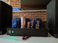
Just got my 50k pot in today and finished up the wiring. For now I ended up only adding the solid state rectifier switch. Might mess around with other configurations in the future.
This amp sound a whole lot better with the right pot, might tighter sound and a whole lot more bass. I am very pleased with the sound now, as of now zero him.
All right guys,
I had two 150 ohm 5 watt resistors in a bag of parts so I wired those up today with the 560, so now 710 ohms Excuse my lack of understanding with this stuff. I took some more measurements today.
R4 400 vdc
R17 20
R27 20
28
Current at cathode- 28ma
400-20=380x.028= 10.6 watts
I did blow the fuse after about 15 20 min
I am really trying to wrap my head around this. Tube was still glowing red as was the other 6l6
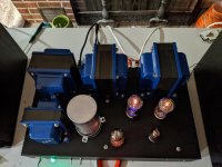
Here is a picture on how I added the two 150 watts resistors, there are 560s on the back? Should be ok this way?
I had two 150 ohm 5 watt resistors in a bag of parts so I wired those up today with the 560, so now 710 ohms Excuse my lack of understanding with this stuff. I took some more measurements today.
R4 400 vdc
R17 20
R27 20
28
Current at cathode- 28ma
400-20=380x.028= 10.6 watts
I did blow the fuse after about 15 20 min
I am really trying to wrap my head around this. Tube was still glowing red as was the other 6l6
Here is a picture on how I added the two 150 watts resistors, there are 560s on the back? Should be ok this way?
Attachments
Last edited:
It looks like you wired the resistors in parallel, not in series. The effective resistance in parallel would be around 118 ohms. 20 volts at 118 ohms would be 169 mA per tube. You may have blown the output tubes.
Thanks for the reply,
I pulled them out but haven't tried to fire it up yet. I'm just going to wait until I get the right value resistor in there. I should have looked me into this then just soldering them in there. I'll get this stuff figured out sooner or later. I'm used to dealing with more straightforward wiring.
- Status
- This old topic is closed. If you want to reopen this topic, contact a moderator using the "Report Post" button.
- Home
- More Vendors...
- Tubelab
- SSE Checkout