Hi all,
I have built a guitar amp and I am having some issues with supplying v1 with DC.
I basically took a Mesa Boogie design from their Rectifier series but it is too noisy in my case.
The setup is: 6.3V heater supply to full wave bridge rectifier( uf5408) to 10000uf. I even upped the filter to 30000uf without success.
Where am I getting all this noise from, especially when Mesa Boogie is selling this design commercially?
Where am I getting all this noise from, especially when Mesa Boogie is selling this design commercially?
By design, I am guessing you built a circuit from the schematic. I further guess you did not build it on an identical circuit board and layout. Did you use Mesa iron? And are the transformers angled to each other?
I am not picking on you, just pointing out there is a lot more to an amp than the schematic.
Even though it is a buzz rather than a tone, is it a 50Hz buzz or a 100 Hz buzz?
Do ANY of the controls have ANY effect on the noise? tone level etc.
Just a thought, did you tie either the -ve or +ve to ground ... not on the 6.3v AC side!
Most manufacturers don't bother with DC heaters as if a valve that doesn't leak is employed, there is no hum/buzz from the heaters.
Check the star point for your grounds. They should all go to the same point; the first tank/smoothing capacitors ground.
Most manufacturers don't bother with DC heaters as if a valve that doesn't leak is employed, there is no hum/buzz from the heaters.
Check the star point for your grounds. They should all go to the same point; the first tank/smoothing capacitors ground.
Printer I do not have the big cap bypassed with a small one, which value do you propose?
Enzo I get your point. Thee amp is a hot rodded Marshall jmp 2203, I copied an original chassis. Only the heaters for V1 are copied from a Mesa schematic. Transformers are angled Marshall clones.
The buzz is 100 hZ. The master volume controle the buzz. The preamp volume alsof controle part of it ( V1a). Pulling V1 gets rid of the buzz. The tone controle alsof work on the buzz.
Jon I tried all the grounding schemes I could think of: center tap on AC side, artificial center tap on DC side, both, grounding + of - at DC side, nothing helps.
The amp is quiet when V1 is removed so I think the other grounding must be ok.
I would try 0.1uF. I am not 100% certain on your description of the noise but this is just one thing not mentioned yet. It is for high frequency noise. Now reading the posts I think you are dealing with lower frequencies. Still not a bad idea trying the small cap. Removing V1 and the noise going away does not signify the grounding is OK. I had an amp where the hum went away when the first tube was removed. In the end it was something to do with the input jack grounding, sorry it was a long time ago and that is all I remember. Try removing the input jacks from the chassis.
In Merlin Blencowe's book, he talks about a buzz problem caused by rectifying an AC heater winding into DC. The problem is that the (rectifier) diodes flow abrupt, short, bursts of current, and this puts "notches" in the AC waveform of the heater winding....the heaters for V1 are copied from a Mesa schematic...
Sharp features like these notches represent relatively high frequencies ("buzz"), and because the heater winding is on the same transformer as the HT, this buzz now shows up on all the transformer windings, and can make the whole guitar amp buzz.
I can think of a few ways of testing if this is the source of your buzz problem. Perhaps the easiest one is to temporarily disconnect your V1 heater power, and then use an external DC source to temporarily power V1's heater. A 6 volt DC power supply, or even four "D" cells in series would do. If this makes the buzz go away, you have your answer.
Compared to the old-fashioned "four diodes + big cap at 60 Hz" approach, one of today's cheap little switch-mode DC power supplies is far, far, far better at providing clean DC heater power. Even for a single 12AX7, it takes a LOT of filtering to supply clean DC using the old-fashioned approach. A single electrolytic cap won't come near what you need.
Marshall engineers didn't have the option to use a cheap little SMPS for V1 heater power back in the 1960s, because they didn't exist back then. But you are lucky, because you do have this option now!
You're unlikely to find a 6.3 VDC switch-mode power supply, but there are a few options. The simplest one is to just run a 6 V DC power supply, which you can buy. Or get a power supply rated for a little more voltage - 7.5 volts, say - and put a resistor in series to drop the voltage down to 6.3 volts at the tube heater.
Of course, you also have the option to wire V1 to use 12.6 V DC heater power. You can use a 12V DC power supply, or a 15V supply with a series resistor. I've even seen 13V DC power supplies, though I don't think they're common.
-Gnobuddy
JimvDB, I'd suggest you post a schematic of your clone amp (including DC heater and any AC heater humdinger parts and showing connections to 0V), and photos of the 0V connections and heater DC parts. It is highly likely that heater rectification noise currents are getting in to the 0V signal path around V1 circuit stage, or heater voltage spikes are leaking across the V1 heater-cathode and getting in to the V1 grid-cathode circuitry.
Did you run V1 with AC heater and have noticeable hum, or did you just go straight for the DC heater circuit ?
It's worth noting that most input stages have negligible hum with 6Vrms on the heater and nearby wiring, so suppressing DC heater ripple voltage to say 0.6Vrms would be significant - reducing DC ripple further to 0.0006Vrms would have pretty much no extra benefit (but bite you on the bum from causing huge heater winding current spikes).
By the way, I think Enzo was too nice on you - rushing in to cast shadows on other's commercial offerings is naive imho, as you are playing in a very technical space when you diy (compared to building kits with instructions and proven performance).
6.3VAC to single stage of cap(s), at heater current, is typically a terrible waveform. See first image. ANY common impedance (or ESR) in the cap makes those "tips" on the waveform, nasty high harmonics. Even to get this good requires very careful wiring and low-low parasitic resistance. In a neat but but unfortunate layout, 0.6V (600mV) ripple would not surprise me. Mesa may just have more skill/experience than you.
Adding one stage of R-C filtering helps a LOT. And in this case, gets the DC volts nearer 6.3V.
Adding one stage of R-C filtering helps a LOT. And in this case, gets the DC volts nearer 6.3V.
Attachments
I guess you feed the rectifier from the same winding as the other valves' heaters? So I assume that this winding is grounded somewhere? As said before, you need the DC side to be grounded, usually by the negative terminal. As this is impossible simultaneously, you need to follow Gnobuddy's advice and add a small 12 Vdc SMPS to supply the 1st tube's heater.
OTOH, have you tried to feed this tube's heater from 6.3 Vac as it is usually done?
Best regards!
OTOH, have you tried to feed this tube's heater from 6.3 Vac as it is usually done?
Best regards!
Any SMPS will do now days. China has many switchers to buck the voltage down to where you want.
LM2596S 3A Adjustable DC-DC Step Down Converter Buck J8Y7 Regulat Voltage M P7O8 | eBay
Or a step up with a small 5V phone adapter.
MT3608 Power Supply DC-DC Voltage Step Up Adjustable Boost Converter Module -/ | eBay
LM2596S 3A Adjustable DC-DC Step Down Converter Buck J8Y7 Regulat Voltage M P7O8 | eBay
Or a step up with a small 5V phone adapter.
MT3608 Power Supply DC-DC Voltage Step Up Adjustable Boost Converter Module -/ | eBay
Last edited:
I hooked V1 up to good DC, a 6v lantern battery. And what do you know.. it still hummed/buzzed!
I also got some radio stations in crystal clear. I forgot to tell this also happened with the rectifier and the big cap.
Can the humbuzz be radio interference?
On AC there is no radio but the amp hums a little bit, thats why I tried to go for DC heaters.
I also got some radio stations in crystal clear. I forgot to tell this also happened with the rectifier and the big cap.
Can the humbuzz be radio interference?
On AC there is no radio but the amp hums a little bit, thats why I tried to go for DC heaters.
A very useful (though frustrating!) result. Now you know it's not the DC heater power causing the buzz.I hooked V1 up to good DC, a 6v lantern battery. And what do you know.. it still hummed/buzzed!
Do you have a grid stopper on every valve? If not, try adding them.I also got some radio stations in crystal clear.
An amplifier that's oscillating wildly, for whatever reason, can also pick up radio stations. Depending on the cause of oscillation, adding grid stoppers to all valves might help here too.
This confirms that the DC heater power isn't the primary problem you're dealing with.I forgot to tell this also happened with the rectifier and the big cap.
Old-fashioned long fluorescent lights ("tube lights"), and even older-fashioned neon sign lighting, can cause very nasty hum / buzz pickup. But few of us have those things in our homes any longer.Can the humbuzz be radio interference?
Are you sure everything that should be grounded, is actually grounded? Outer braid of all shielded cables? Metal shell of all pots?
I don't have an answer for that, maybe someone else will figure it out.On AC there is no radio

-Gnobuddy
I guess both of them don't provide insulation between input and output. Hence, problem not solved, I'd say.
Best regards!
Any SMPS's for small electronics like phones or laptops generally have galvanic isolation from the line so these switchers do not need to have the output isolated from the input.
I agree, without those we're totally in the dark. This is a DIY build of a high-gain circuit, and there are any number of potential causes that might explain the circuit's misbehaviour.Schematic and photos...
-Gnobuddy
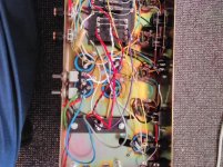
It is basically this schematic with a few changes : all attenuators are taken out, all gain stages have cathode bypass caps.
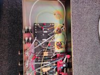
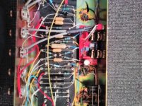
I hope the photo resolution is high enough to see what needs to be seen.
I added grid stoppers and they do seem to help a bit with the hum ( heaters on AC) but I took them out because they robbed highs. I used 34k. Amp was not completely hum free though.
I hope the photo resolution is high enough to see what needs to be seen.
I added grid stoppers and they do seem to help a bit with the hum ( heaters on AC) but I took them out because they robbed highs. I used 34k. Amp was not completely hum free though.
Attachments
- Status
- This old topic is closed. If you want to reopen this topic, contact a moderator using the "Report Post" button.
- Home
- Live Sound
- Instruments and Amps
- DC heater noise