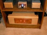
Put together an amp for the summer. It genreates almost no heat. Sounds great, but with 13 volt rails and a bias on each section of 300 ma, it limited to high efficiency speakers.
Here a picture of it in operation. Above is a Tao line stage, thanks to Steve Eddy, a line power supply, and the raw supply for a Passdiy Pearl phono.
Here a picture of it in operation. Above is a Tao line stage, thanks to Steve Eddy, a line power supply, and the raw supply for a Passdiy Pearl phono.
Attachments

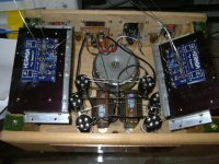
Stuffed Circuit Boards
Boards are from PCB-Design, thanks Kristijan!
Stuffed with modern transistors, and for now all values are close to the suggested values from KK. The resistors are mostly hand matched Allen Bradley 1/4 watt carbon comp. The power resistors are Dale LVR-5, special low inductance, non-magnetic current sensing.
Attachments
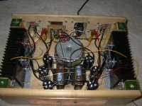
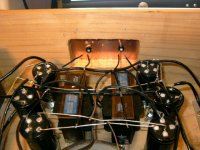
Power Supply
A 250 watt, 10 volt dual from Victoria Magnetics. Two rails recitified with 20 amp, 100 volt Schottkies.
Capacitors are all 25 volt, 47,000 ufd 4 pole Jensen. Gives 288,000 ufd for a 5 watt amp.
The 4 pole caps place a little isolation into the ground plane. The ground plane is split into three sections. The first has the rectifiers and input to first cap. The second has the output of the first caps, the chokes, and input into the second cap. The final ground loop is the output of the second caps and the actual circuitry.
The two boards and the raw suppply all go to ground through a double diode to provide a little more ground isolation.
Details on these four pole caps is listed on the Jensen website, they are very trick.
Attachments
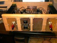
Business end
El Cheapo 5 ways, same for RCA's. 15 amp Schurter input, dual amp amp switch with sides tied together. Extra panel is for fan if needed.
Switches are to select either output or 25 watt 15 ohm power resistors. The power resistors allow hooking up for runnig in playing without disturbing anyone.
El Cheapo 5 ways, same for RCA's. 15 amp Schurter input, dual amp amp switch with sides tied together. Extra panel is for fan if needed.
Switches are to select either output or 25 watt 15 ohm power resistors. The power resistors allow hooking up for runnig in playing without disturbing anyone.
Attachments
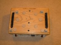
Chokes
The chokes are 2.7 mH, 6 amp. Found surplus at a local parts store. The four pole caps are why there is so much wiring. It is like connecting 12 caps instead of 6.
Got crooked on the LED's. Bin said difused blue, they are red. But looks nice on the copper faceplate.
George
The chokes are 2.7 mH, 6 amp. Found surplus at a local parts store. The four pole caps are why there is so much wiring. It is like connecting 12 caps instead of 6.
Got crooked on the LED's. Bin said difused blue, they are red. But looks nice on the copper faceplate.
George
Attachments
Nice work!
I like the way you mounted those PCBs and the power transistors to the heat sink. I think this is a good way to fix it all and prevent movement of the PCB relative to the power transistors, which ads greatly to the reliability. Have to remember that one!
Jan Didden
I like the way you mounted those PCBs and the power transistors to the heat sink. I think this is a good way to fix it all and prevent movement of the PCB relative to the power transistors, which ads greatly to the reliability. Have to remember that one!
Jan Didden
Next amp will be the Aleph XM. I am waiting on the boards and still working on the box.MikeW said:Nice job. I love the wood. Thanks again for the extra parts.
What is next?
But I am building a new linestage, and two power supplies first. I cannot fit all the chokes and caps I want in the size used now. Going to larger, Eagle boxes.
George
I have almost finished mine.
details are there:
http://belinfabien.free.fr/amplificateur/le monstre/monstre.htm
and there:
http://belinfabien.free.fr/amplificateur/le monstre/boitier.htm
details are there:
http://belinfabien.free.fr/amplificateur/le monstre/monstre.htm
and there:
http://belinfabien.free.fr/amplificateur/le monstre/boitier.htm
Hi panel head,
Are you using new or old transistor? If you are using the new one, do you face the problem of low output power? Mine build with new transistor and the output is too low without any preamp. The output bias is only 150mA per rail. What about yours. Pls advise.
Regards,
Ipanema
Are you using new or old transistor? If you are using the new one, do you face the problem of low output power? Mine build with new transistor and the output is too low without any preamp. The output bias is only 150mA per rail. What about yours. Pls advise.
Regards,
Ipanema
Very nice work Panelhead!
I see that you use the boards of Kristian and i have a question for you if possible.
I have 2 boards too, and what i see on my boards is that the connection pads (C, E, B) on the boards from some transistors are not in the same direction (order) as the connection leads of the transistors.
For example, from left to right: the PCB order says C, E, B and the transistor order (datasheet) says C.B,E.
For this reason the three transistorleads must be changed before soldering them on the PCB.
Did you notice that too?
I hope you anderstand my question. If not, i try to do better.
- Status
- This old topic is closed. If you want to reopen this topic, contact a moderator using the "Report Post" button.
- Home
- Amplifiers
- Solid State
- A New Le Monstre Lives