Hi Guys
can anyone please design a passive crossover for me , I have the following 6inch PP cone driver and 25mm soft dome tweeter that i intend to mount on a 180mm X 350mm baffle net volume 13L with a f3 of 50hz, I think 1800-2200Hz will a good crossover-point although i am open to suggestions. I am saving money for Omnimic v2 and will hopefully buy it in 2 months time and then i can generate my own graphs, but till then i would really love to have something to play my music on, I had downloaded the VituixCAD2 but could never trace the spl or impedance properly maybe due to poor image quality ...
thanks guys
Attachments
What program are you using to trace? I cant find frd and zma files anywhere
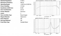
Jbl 2235H
BMS 4592 mid
RAAL Tweeter 140-15D
Raal "Original 140-15D" Ribbon Tweeter with Amorphous Core
Overview
Components - 2235H
Jbl 2235H
BMS 4592 mid
RAAL Tweeter 140-15D
Raal "Original 140-15D" Ribbon Tweeter with Amorphous Core
Overview
Components - 2235H
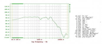
I managed to trace them for you. In order to post them here I needed to append .txt to each file.
AllenB you are really kind, thank you.
Can you please direct me towards a tutorial so that I can also learn on how to make these files ...
Do you mean to make the crossover? Big question.
You say you have VituixCad. OK, that is good. First on the driver tab you want to add one driver so there are now two drivers. Each driver will need an .frd and a .zma
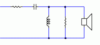
Now switch to the crossover tab. Make up a simple circuit (eg below). Adjust values to aim towards level and even responses from your woofer and tweeter.
Keep posting back with screenshots of VC so we can make suggestions.
You say you have VituixCad. OK, that is good. First on the driver tab you want to add one driver so there are now two drivers. Each driver will need an .frd and a .zma
If you post a link to the woofer datasheet, we can trace this. Now you have four files. Put them in a folder. Bring them into the drivers one at a time.PeteMcK said:need the impedance plot of the woofer as well, manufacturer's data sheet is OK
Now switch to the crossover tab. Make up a simple circuit (eg below). Adjust values to aim towards level and even responses from your woofer and tweeter.
Keep posting back with screenshots of VC so we can make suggestions.
Attachments
Do you mean to make the crossover? Big question.
You say you have VituixCad. OK, that is good. First on the driver tab you want to add one driver so there are now two drivers. Each driver will need an .frd and a .zma
If you post a link to the woofer datasheet, we can trace this. Now you have four files. Put them in a folder. Bring them into the drivers one at a time.
Now switch to the crossover tab. Make up a simple circuit (eg below). Adjust values to aim towards level and even responses from your woofer and tweeter.
Keep posting back with screenshots of VC so we can make suggestions.
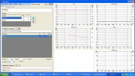
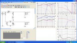
I added the FRD files that you made for me , and added the zma for the tweeter as well , should i seeing something on the graphs on the right side ..??
Thankyou
Attachments
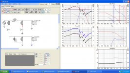
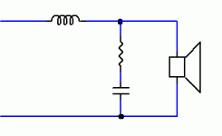
That's it. Now, the two red dots on the crossover show nodes that are disconnected. Put a wire between them.
The leftmost 10 ohm resistor is too high in value. If you reduce this, the tweeter response will rise compared to the woofer.
If you right click on the response plot (the one at the top in the middle of the screen marked 'SPL'), you can choose (umm, what's it called) optimiser I think. Set the level near say, 87, Linkwitz-Riley highpass, order = 4, lowpass=none. The pink trace is a target. Adjust your tweeter components so that the blue line approaches the pink one.
Last edited:
Reduced 10ohms to 1ohms and did as you asked in optimizer , i read somewhere that the tweeter needs to be fliped did that too...That's it. Now, the two red dots on the crossover show nodes that are disconnected. Put a wire between them.
The leftmost 10 ohm resistor is too high in value. If you reduce this, the tweeter response will rise compared to the woofer.
If you right click on the response plot (the one at the top in the middle of the screen marked 'SPL'), you can choose (umm, what's it called) optimiser I think. Set the level near say, 87, Linkwitz-Riley highpass, order = 4, lowpass=none. The pink trace is a target. Adjust your tweeter components so that the blue line approaches the pink one.
Attachments
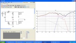

Nicely done. Look at the phase plot (top right of screen). Then flip. Whichever one brings red and blue closer near the crossover, is preferred at this stage. You only need to right click the driver and choose inverti read somewhere that the tweeter needs to be fliped did that too...
")
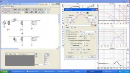
So where will you cross? It appears you're heading toward 2k2Hz and I guess this could work. See the small woofer peak at 3k3Hz? You want this to be down a fair way. So, can you set an optimiser curve that is lowpass for the woofer, is 87dB through the lows, is 81dB at the crossover frequency, and is somewhere in the 60s or less at 3k3Hz? Use the filter order to change how far it is down at 3k3Hz. This sets it for now.
Now you can match this for the tweeter. The needed circuit will be what it takes to make this work.
Also, leave the low bass up above 87dB. This helps manage exterior box effects.
ONB there is something wrong with the tweeter zma-file and the woofer impedance is missing. Furthermore you should simulate the effect of the baffle with the diffraction tool in VCAD. The woofer impedance file is enclosed (simulated with TSP of woofer).
Regards
Heinrich
Regards
Heinrich
Attachments
This is a step in the right direction.
You may find things easier with both tweeter resistors placed next to the tweeter?
Recall what has been said about the baffle/box. Your bass would be good at 91dB, and the rest at 87. One suggestion was to apply a baffle simulation to your woofer response file, if you do then you can aim for flat, otherwise you would need to imagine the curve I'm describing.
- Status
- This old topic is closed. If you want to reopen this topic, contact a moderator using the "Report Post" button.
- Home
- Loudspeakers
- Multi-Way
- 2way passive cross over help