I have a computer sub box with two full range speakers, the PS was blown and trying to convert another ic in the circuit, I pulled a few parts to accommodate the modifications but my problem is I’m not getting much amperage. The voltage is 16vdc+/- but when attenuating it chips out. If I change the feedback resistor I’ll get a lower volt (10v+/-) with more amp that plays a bit higher but will still chip out if given more attenuation.
Is there any ic that can drive the switching transformer without an external mosfet/regulator that can produce more amp in a 4pin dip package?
I’m currently using the TNY268.
Is there any ic that can drive the switching transformer without an external mosfet/regulator that can produce more amp in a 4pin dip package?
I’m currently using the TNY268.
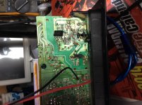
Attachments
Is there anything else that can be said that is helpful?
Is there any electronics engineers in this forum, someone who is somewhat knowledgeable in smps circuitry?
Hi Formas,
Regarding your question above, Osvaldo is from what I have seen in many previous postings very competent in SMPS and as far as I can read a very well educated electronic engineer. So, yes!
") And, he is normally very helpful.
And, he is normally very helpful.Perhaps you did not provide the right information for Osvaldo to give you a precise reply!
OK:
You have a sub-box with a +/-16V power supply that is burned. Was the now dead power supply an SMPS or with an ordinary net-transformer?If it was with an ordinary net-transformer, an SMPS chip will not help you. If it was an SMPS, which chip (if based on a chip) was used to drive the SMPS?
+/-16V rails corresponds to 32W in 4 Ohm with normal SE coupling and if the amplifier is class D. With BTL coupling, four time as much or 64W in 2 Ohm. I assume a sub-box to be mono, can you see on which chip the amplifier is based?
You ask us which IC in a 4 pin DIP package (I guess you mean 8 pin DIP package as also TNY263 is DIP-7/8 housing), without use of external switches, you can use to generate such power. It starts looking like you may need an external switch for that power level. Was the original power supply based on a DIP-8 chip?
Please give us some more information about the previous power supply design, the amplifier chip and the speaker impedance if you want our help.
Last edited:
Ahh, yes the DIP-8 is correct (just that 4 pins are really what there is as the source are on the remaining pins which I often just use one).
The original chip was CR18818(China) and drives a mosfet/regulator, also I’m assuming the working voltages as the rail caps are 25v. The audio output is made up of three IC’s (left, right and sub).
With just the basic primary circuit for the modification for using the TNY268 I’ve gotten 16v+/- without any modifications to the secondary circuit, but somewhat with even that voltage it’s under amped.
My question is really how best can I get more amperage with the TNY268 driving the transformer direct or if there is a more common chip that I could use to drive it with a simple circuit design for the primary.
***and the smps transformer is a four pin primary and base on the basic TNY268 diagram I used I don’t know if the coils are been driven effectively.
I believe in order to get more Amperes You'll need to re-design the SMPS and use a bigger switching transformer, unless this one is over dimensioned and can handle more current.
That’s the original transformer that used to operate the equipment, I think I can use it if I know how, or can drive it harder.
Scaling up an SMPS involves more than just cramming more amperage thru the transformer. To scale a topology, you need a bigger core, better winding technique, more capable IGBT’s, and a proper method of driving them at the new current level (without sacrificing speed). The original circuit layout might not even work. The secondary side is a bit easier, but you have to scale it too.
You may be able to get more out of a given trafo and set of IGBTs if you go from a hard-switched design to an LLC. But that’s a whole new design problem and comes with some constraints that may or may not work fo you. And you would need to rewind it because the output voltage will change (not strictly turns ratio dependent). If it’s already resonant mode it may already be maxed out in terms of what you can get.
You may be able to get more out of a given trafo and set of IGBTs if you go from a hard-switched design to an LLC. But that’s a whole new design problem and comes with some constraints that may or may not work fo you. And you would need to rewind it because the output voltage will change (not strictly turns ratio dependent). If it’s already resonant mode it may already be maxed out in terms of what you can get.
I kinda understand some of what is explained but I’m just trying to be theoretical about the fact that that was the same transformer that was working, I just would like to know if there’s this “magic” chip that comes with a schematic that can drive the transformer or if there’s one with external mosfet/regulator.
I’ve just gotten a working unit and the voltage are 13.4v+/- for the rails.
I’m getting 16v by just applying the TNY268 but when testing different resistors that drives the optocoupler via the TL431 volts I had 10v that played stronger than the 16v hence I believe that at higher voltage I’m losing current.
Can I use a potentiometer to find the 13v and see if the audio circuit will hold steady at that rating as the original design?
Ahh, yes the DIP-8 is correct (just that 4 pins are really what there is as the source are on the remaining pins which I often just use one).
The original chip was CR18818(China) and drives a mosfet/regulator, also I’m assuming the working voltages as the rail caps are 25v. The audio output is made up of three IC’s (left, right and sub).
With just the basic primary circuit for the modification for using the TNY268 I’ve gotten 16v+/- without any modifications to the secondary circuit, but somewhat with even that voltage it’s under amped.
My question is really how best can I get more amperage with the TNY268 driving the transformer direct or if there is a more common chip that I could use to drive it with a simple circuit design for the primary.
***and the smps transformer is a four pin primary and base on the basic TNY268 diagram I used I don’t know if the coils are been driven effectively.
Many thanks for the information.
I found a photo of the CR18818 IC and mentioning of a "LCD power management chip IC". I found no datasheet.
The thing is that an SMPS transformer is designed to match the driving circuit. That means driving "topology" (flyback, forward......), operational frequency (50KHz-150KHz typically), evidently output power and output voltage. A traditional power supply with a net-transformer is simple and we can often find generic replacing parts. For an SMPS, you need to know all this to find replacing parts and with designs and parts from Asia that is often a problem as we have no datasheets we can understand at least.
For instance, if you operate an SMPS circuit at higher frequency than it is designed for, losses in the transformer and switching diodes become high and it won't work well. If you operate an SMPS transformer at too low frequency, it will saturate and work very poorly if your driving circuit will survive at all. If you operate a transformer that is designed for forward topology in flyback mode, you will typically end up with too little power.
As you have a broken down SMPS with parts we know little about and you have only limited knowledge of SMPS technology, the chance that you can modify what remains of the original SMPS is very small. You took a chance with a TNY268 and it worked somewhat but not well for the reasons explained above. A DIP-8 chip alone for a power level that may well be above 100W sounds a priori difficult.
Your realistic possibilities:
Your guess of rail voltages in the range 16V-20V sounds right with rail capacitors rated at 25V. You have three amplifier chips (that may be class AB with the symmetrical supply rails used) which indicates a total power need of above 100W. If you tell us the type of the chips and the impedance of the speakers we can make a good estimate.
You can disable the old SMPS by removing the essential components from the PCB. You then need a new power supply to replace the old one. SMPS with dual rail voltages is technically possible but they are rare, as not often used, and they tend to be expensive. You can hardly rely on the new power supply to fit in the cabinet with the amplifier and you will need a separate (external) power supply housing.
With a traditional net-transformer you need 2x15V on the secondary. I have been lucky to find such double-winding transformers in old smaller amplifiers that used dual symmetrical rail voltages. You will probably need around 120VA capacity of the transformer.
Before we go further with details, first you need to decide if you want to repair it with an external power supply?
Last edited:
It is a subwoofer box so there is ample space to house a linear transformer, so if I use say a 15-0-15 transformer and remove the switching transformer (it is a center tap secondary) and wire in on the ac and ground that would be ok? If yes, what amperage transformer would be needed?
The three output IC’s are SI2030AV white some Chinese letters. I’m not sure if it’s the Chinese equivalent to TDA2030 but it’s same look and package.
If it is, the operating volts says 6-36v, so my modification has my current problem, “A CURRENT PROBLEM” (pun intended).
The three output IC’s are SI2030AV white some Chinese letters. I’m not sure if it’s the Chinese equivalent to TDA2030 but it’s same look and package.
If it is, the operating volts says 6-36v, so my modification has my current problem, “A CURRENT PROBLEM” (pun intended).
If the original was designed right the transformer is at its limit already, not oversized. Perhaps you could run it at a higher frequency for more power throughput, but then you must know the grade of ferrite and its performance curve with frequency to design safely. Overloading ferrite will cause eventual thermal run-away as the material degrades when run over-temperature for extended periods, which reduces efficiency, leading to more heating, etc etc.That’s the original transformer that used to operate the equipment, I think I can use it if I know how, or can drive it harder.
Basically good SMPS design is an advanced art, trying to eeek more performance from the magnetics of a commercial PSU isn't likely to have a happy ending.
This thing uses gainclone chips, and only 16 to 20 volts on a rail? I would be inclined to look for fully built enclosed frame switching supplies on the surplus market, and just put two in series to get +/-V. 15 volters would probably work, as would 19 volt laptop supplies if you can still find them. You could probably buy them from Digikey for stupid money, but I’ve seen units going for $20 or less from surplus houses like BG Micro. A unit designed to actually run continuous loads will be far more reliable than something in a piece of cheap consumer audio gear.
The power in a SMPS is related to the volume of the transformer (or fly back mutually coupled inductors) and in the topology chosen by the designer. It is rare that the manufacturer uses a larger core size than the really needed, so it is rare you can get more power from the trafo than the permissible heat evacuation permits. Perhaps increasing or adding some air flow may allow to increase the current and gain some power from it, supposing that the primary semiconductors are able to handle the new conditions of peak current(s), duty cycle and heat evacuation.
There is a chance if you have a kind of full wave rectifier at the secondary, mutating from it to a current doubler, but still at the expense of overloading or excessive stresses on primary semiconductors.
There is a chance if you have a kind of full wave rectifier at the secondary, mutating from it to a current doubler, but still at the expense of overloading or excessive stresses on primary semiconductors.
What does it boils down to?Agree and add: the short answer is:
1) no, you can not "increase power" from your current supply.
2) you need a new, larger supply.
You may run in circles many times, it boils down to this.
I’m not trying to make a major modification, besides the same power supply was what was working the thing before there was an electricity surge. And the original IC blown along with the fet driving the transformer.
I’m simple asking if you guys have a simple circuit layout both internal or external mosfet circuit that could drive the primary side of the transformer.
When I say more power, I’m not even getting what the circuitry was designed at.
You guys let it seems that this was a cell phone charger and I want to power an amplifier with it.
The so called transformer (Actually it ISN'T, is a coupled inductor, not the same as a transformer) depends on voltage available (Net * 1.414), frequency and power. So it will be difficult to find an IC that be capable of driving the "transformer" without knowing those data. In other hand, the power available I doubt that be more than 10W, only sufficient for a PC speaker. Still worse if it is quasi-resonant or a blocking oscillator.
I’m not trying to get more power, I’m just not getting what it was designed to deliver, how can I get to drive the transformer harder?The power in a SMPS is related to the volume of the transformer (or fly back mutually coupled inductors) and in the topology chosen by the designer. It is rare that the manufacturer uses a larger core size than the really needed, so it is rare you can get more power from the trafo than the permissible heat evacuation permits. Perhaps increasing or adding some air flow may allow to increase the current and gain some power from it, supposing that the primary semiconductors are able to handle the new conditions of peak current(s), duty cycle and heat evacuation.
There is a chance if you have a kind of full wave rectifier at the secondary, mutating from it to a current doubler, but still at the expense of overloading or excessive stresses on primary semiconductors.
Is there an IC layout with a regulator schematic that uses a few external parts?
Is there a known IC that can drive it without an external mosfet and a few parts?
It is a subwoofer box so there is ample space to house a linear transformer, so if I use say a 15-0-15 transformer and remove the switching transformer (it is a center tap secondary) and wire in on the ac and ground that would be ok? If yes, what amperage transformer would be needed?
The three output IC’s are SI2030AV white some Chinese letters. I’m not sure if it’s the Chinese equivalent to TDA2030 but it’s same look and package.
If it is, the operating volts says 6-36v, so my modification has my current problem, “A CURRENT PROBLEM” (pun intended).
So would a linear center tap transformer (15-0-15) work if I wired it to the secondary (removing the smps of course) if yes what amp transformer?
- Status
- This old topic is closed. If you want to reopen this topic, contact a moderator using the "Report Post" button.
- Home
- Amplifiers
- Power Supplies
- How to increase amperage in SMPS circuit?