You could make your own by measurement. Or trace the factory graphs.
I have now traced spl for seas ht1396,and working now in Vituixcad.
Does this crossover look okey,or is it totally a disaster? ;-)
Trying too learn ;-)
Attachments
You might find it helpful to show the individual driver responses.
I'm not sure I see what you are aiming at with the resistors in the mid circuit?
I did get this advice from gringoaudio,but i did a change in the tweeter.
here is my traced factory spl file(seas tweeter)! hope i am doing it rigt?
Bad language,i am from sweden!
")
Attachments
Last edited:
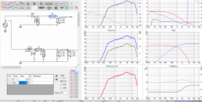
Wrt the file, I'm not on the right computer atm, but I'm looking at the text file. It appears that it should function but I have a concern.
It appears you have traced in a way that the tracing program was expecting an impedance. The thing with impedances is that some people like then on a linear vertical scale and some like them log. How can you be sure that this SPL has been done right.
The way I would do it is after setting the bounds in the trace setup, move the cursor to some intermediate value and make sure it fits.
Wrt the crossover what is your goal, what are you looking to see when you change the values?
Wrt the file, I'm not on the right computer atm, but I'm looking at the text file. It appears that it should function but I have a concern.
It appears you have traced in a way that the tracing program was expecting an impedance. The thing with impedances is that some people like then on a linear vertical scale and some like them log. How can you be sure that this SPL has been done right.
The way I would do it is after setting the bounds in the trace setup, move the cursor to some intermediate value and make sure it fits.
Wrt the crossover what is your goal, what are you looking to see when you change the values?
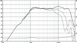
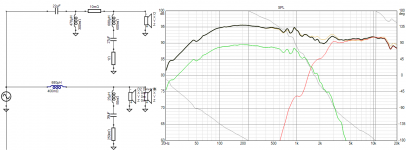
Here is the graph i have traced,i am not sure that is a good trace!
that i would think is,the crossover graph would be horizontal and a good xo point,but that is not the case.
Attachments
Right click on your response plot in VC and open an overlay (the response file) so that you can see it and compare to the image you've shown.
Resistors reduce levels. They do other things, but the way you have them near your mids they would be bringing the level down too much. Can you try it without them? Work out where to go from there.
Resistors reduce levels. They do other things, but the way you have them near your mids they would be bringing the level down too much. Can you try it without them? Work out where to go from there.
Right click on your response plot in VC and open an overlay (the response file) so that you can see it and compare to the image you've shown.
Resistors reduce levels. They do other things, but the way you have them near your mids they would be bringing the level down too much. Can you try it without them? Work out where to go from there.
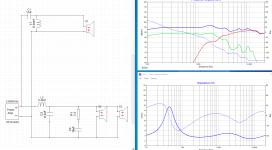
Now i have found frd and zma driver,this is what the dayton support thinks about a crossover for me!
I have a thouhgt! can a little bit too much cabinet volume,make echo noises ?
Attachments
If the damping material inside of your cabinet does what I think it should, you should have no problems.
Your crossover is looking much better. Notice the mid driver response up above the crossover frequency. Larger drivers don't behave at much higher frequencies. It would be better to reduce that further so the tweeter is on its own up there.
Right click on your response plot and choose 'optimiser'. From here you can place a target response line on your chart. The uppermost text box is for the level of the target. In your case I would begin at maybe 88.5dB, Linkwitz-Riley and second order low-pass for starters.

If the damping material inside of your cabinet does what I think it should, you should have no problems.
Your crossover is looking much better. Notice the mid driver response up above the crossover frequency. Larger drivers don't behave at much higher frequencies. It would be better to reduce that further so the tweeter is on its own up there.
Right click on your response plot and choose 'optimiser'. From here you can place a target response line on your chart. The uppermost text box is for the level of the target. In your case I would begin at maybe 88.5dB, Linkwitz-Riley and second order low-pass for starters.
Thanks for your help,it is not easy.
here you have my dxo file for xsim,if you want to play with it.
Attachments
Could you post both the response files and both the impedance files (or a link to the plots would be ok).
Here do you have a zipfile with frd and zma!
it is interesting to see how you have been doing it!
Attachments
My current confidence level is based on the data, which is basic, but can be improved upon. There is more generic data available. You want to know what angle is best for listening.
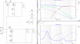
Your tweeter trace had no phase data so I gave it minimum phase. This means I had the phase fit the response. Normally there is extra phase information that is also needed but this is the limitation when you trace.
The layout of the crossover can be changed to bring the same results, but this layout seemed to fit without too much trouble.
Attachments
My current confidence level is based on the data, which is basic, but can be improved upon. There is more generic data available. You want to know what angle is best for listening.
Your tweeter trace had no phase data so I gave it minimum phase. This means I had the phase fit the response. Normally there is extra phase information that is also needed but this is the limitation when you trace.
The layout of the crossover can be changed to bring the same results, but this layout seemed to fit without too much trouble.
That look really nice,the thing is that i am building a center speaker,and then i have 2 piece of the rs150(parallell wired) 😜,i didnt wrote that last time,i am sorry for that.
No problem. Ideally, this channel should be the same as the others. The baffle circumstances are uncertain. The horizontal dispersion is dependent on the driver relationships. I was challenged keeping the impedance close to 3Ω. This is because I wanted max level out of the tweeter and it is a 4Ω driver.
Attachments
No problem. Ideally, this channel should be the same as the others. The baffle circumstances are uncertain. The horizontal dispersion is dependent on the driver relationships. I was challenged keeping the impedance close to 3Ω. This is because I wanted max level out of the tweeter and it is a 4Ω driver.
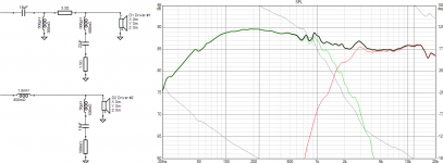
Thats look really good,i dont know if my trace on the tweeter is 100%.
But i have tested in xsim(your crossover) but the curve doesnt look the same at all.
Your crossover does drop from xo point around 1600-1700hz too under 5k hz about 60db.
xsim looks like this
Attachments
- Status
- This old topic is closed. If you want to reopen this topic, contact a moderator using the "Report Post" button.
- Home
- Design & Build
- Software Tools
- frd zma