So I'm working on a 12b4 based low-mu preamp design. I'm pretty new to the DIY audio world, but I've kind of fallen in head first. I have a lot of electronics experience, but not with tube power supplies.
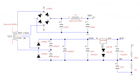
Anyway, here is a schematic that I've been working on. It's a 320V main, with a 6.3V DC heater supply (biased up by 38V, which apparently the 12b4 tubes like). I decided to go with a voltage doubler on the 6.3VAC winding so I'd have enough overhead for the 1085 regulator.
I'd really appreciate some advice/guidance from those of you with some experience here. There are two things that I'm not sure about right off the bat:
1) Is the filtering on the 320V side sufficient?
2) Should I build in some delay to let the tubes warm up before applying the 320V. Right now B+ biases up faster than the 6.3V.
Thanks!
Attachments
A ruff calculation suggests you won't hit anything like 16.6V into the regulator. Maybe not even 12.0V, with enough ripple to embarrass a line-amp.
Also a 1N4007 burns-up on rms current.
When using Silicon rectifiers, if you have a choice 6.3V or a higher heater voltage, always go higher. Given 12B4, I'd even run both in series at 24V, a standard SMPS rating.
Also a 1N4007 burns-up on rms current.
When using Silicon rectifiers, if you have a choice 6.3V or a higher heater voltage, always go higher. Given 12B4, I'd even run both in series at 24V, a standard SMPS rating.
@rayma
The resistor between the doubler and the big filter cap is good, thanks. I'm not totally sure how to calculate the drop there, but it seems like anything less than maybe 50R would work.
@PRR
I'm curious about the specifics of your rough calculation. I've mostly been tinkering with Duncan's "PSU designer II" software, which is where the 16.6V came from.
I think the 4007s are fine for the high voltage side, the current draw should only be a few 10s of mA. But you're right, I should use 5401s or something for the heater side.
I feel a bit limited by transformer options. 6.3V and 5V are pretty ubiquitous values for the secondary winding. I could use an SMPS off of the HV side i guess?
Or maybe I should just get a separate transformer for the heaters?
Set the resistor value by dropping approx. 3V to 4 V across it. There should be enough voltage drop across the regulator left to allow the regulator to work at the lowest AC line voltage without dropping out. If DC current is 300mA, use 3V/.3A = 10R for example.
Whatever you calculate for the resistor power rating, multiply that by at least 4 times, to allow for the ripple voltage drop, and the usual derating factor. If 300mA, power = .3 x .3 x 10 = 0.9W.
Total Pd in the resistor is more like 2W due to ripple drop. Remember, that's being removed from the regulator to a cheap resistor. Then I'd use 10R 5W (or 10W if there's room).
Last edited:
@rayma
Oh... yes obviously. I misunderstood. The two 12b4 heaters draw 0.6A each at 6.3V, so I would need a very high power 3.6-4.8ish ohm resistor. Maybe 20W.
@PRR
I didn't know to pay attention to the source resistance or off-load voltage, thanks. Do you think the 20R load resistance correct for a lin reg?
> pay attention to the source resistance
Everything sags. Hoover Dam sags when all of LA turns on their AC. Small transformers sag more than huge ones. It has to be accounted.
> Do you think the 20R load
The tubes alone are 12V 0.6A which is 20 Ohms. Little different with a regulator. It is a conservative starting point.
Everything sags. Hoover Dam sags when all of LA turns on their AC. Small transformers sag more than huge ones. It has to be accounted.
> Do you think the 20R load
The tubes alone are 12V 0.6A which is 20 Ohms. Little different with a regulator. It is a conservative starting point.
Thanks for your replies. I think I’m starting to get my head around some of the nuances of transformers/rectification/filtering.
I think i’ll start by heating the tubes with the 6.3VAC and see how it sounds. From what I’ve gathered here and elsewhere, the 6.3V AC->DC conversion at 1.2A is a non-trivial problem, and not ideal.
I think i’ll start by heating the tubes with the 6.3VAC and see how it sounds. From what I’ve gathered here and elsewhere, the 6.3V AC->DC conversion at 1.2A is a non-trivial problem, and not ideal.
Total Pd in the resistor is more like 2W due to ripple drop. Remember, that's being removed from the regulator to a cheap resistor. Then I'd use 10R 5W (or 10W if there's room).
On the other hand the regulator's already going to have to be on a large heatsink,
its simpler and cooler to just make that heatsink a bit larger than having a separate power resistor. But such a resistor will reduce the inrush current at startup, that might be important.
If you really are dropping 10V@1.2A across the regulator, that's 12W. That will require a fairly big heat sink. Consider connecting filaments in series and drop ~4V@0.6A, 2.4W. A little more voltage headroom could be squeezed out by using schottky diodes with less forward voltage drop.
- Status
- This old topic is closed. If you want to reopen this topic, contact a moderator using the "Report Post" button.
- Home
- Amplifiers
- Power Supplies
- PS for linestage tube pre-amp (12b4)