I designed and built a 50W tube power amp based around a pair of 6L6GC, but I cannot for the life of me seem to get 50W out of it cleanly. 28-30W is the max I've seen.
The circuit is your everyday push-pull output with a long tail pair phase inverter and a PPI-MV. I've got a Va of 420V (with up to 600mA avail from the PT) into a 4.2k OT and I'm driving an 8 ohm dummy load. Calculations suggest 50W should be easy here.
I'm measuring with a scope and a Fluke RMS meter, where I'll drive the amp with a sine wave and adjust the level to just before I'm clipping the PI input. I'll then bring the MV up until I just before I see clipping on the power tube grids...this always happens when the signal level exceeds the bias voltage (biased cool at 30 to 38mA, -45 and -42Vdc respectively). The Fluke is monitoring the voltage across the 8-ohm dummy load and it's always ~15-15.5 Vac before distortion sets in, which calculates to only 28-30W.
Is there something I'm missing? Everything seems in order here aside from the power output, which makes me think I'm just calculating power wrong. Does power factor in both the + and - signal when we calculate it or just a single phase?
Thanks all!
Please post a schematic.
I have run a Tubelab universal PP driving 6P3S-3 (6L6oid) tubes with UL taps at 400V B+ and a 5K opt and gotten 40W out in AB2 at 8%thd.
I only got 20W before I hit grid current.
With slightly higher B+ and slight lower impedance OPT, I think your output is quite good, depending on what mode you are running (Pentode?, UL, Triode strapped? Other?
What is the screen voltage, and is the 8 ohm load connected to the 8 ohm tapping? What frequency are you testing at?
I just checked and was getting 424V on the screens, 433V on the plate with no signal. Yup, 8 ohm to 8 ohm tap. I've tested at both 350 Hz and 1 kHz and gotten the same result.
With slightly higher B+ and slight lower impedance OPT, I think your output is quite good, depending on what mode you are running (Pentode?, UL, Triode strapped? Other?
I'm running pentode, fixed bias with switchable negative feedback. Nothing fancy. I'll post a schematic here in a bit!
Please post a schematic.
I have run a Tubelab universal PP driving 6P3S-3 (6L6oid) tubes with UL taps at 400V B+ and a 5K opt and gotten 40W out in AB2 at 8%thd.
I only got 20W before I hit grid current.
With slightly higher B+ and slight lower impedance OPT, I think your output is quite good, depending on what mode you are running (Pentode?, UL, Triode strapped? Other?
See attached for the schematic.
Thank you for the vote of confidence, but doesn't your Tubelab specs suggest something is wrong with mine? Ignoring your UL connection for a sec, we can assume an effective 350V B+ into 1.25k should get around 98W peak, or 49W. Factor in the UL being somewhere in between triode and pentode operation and 40W sounds right.
Whereas mine would be an effective 370V or so into 1.05k, which would be 130W peak, or 65W. So 30W seems pretty bad, no?
Attachments
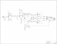
Your schematic is showing the volume pot inside the feedback loop? That usually doesn’t work well....... but it won’t necessarily cause it not to hit full power. It does need to be corrected - unless you really do intend for the pot to adjust open loop gain and not as a master volume (as labeled).
I’m wit the others on the probable causes - either the B+ is dropping like a stone or you don’t have enough Vg2 to support 350mA of peak current.
I’m wit the others on the probable causes - either the B+ is dropping like a stone or you don’t have enough Vg2 to support 350mA of peak current.
Ya, that's more an experiment where I'm trying to test post PI master volumes, just like the 47pF caps from top to wiper. For the power tests, it ends up that this control is full up, and the 'drive' control is what ultimately sets the max clean volume, if that makes sense.
Don't my measurements above rule out the B+ and screen being issues? Seems like those hold up well.
Don't my measurements above rule out the B+ and screen being issues? Seems like those hold up well.
Ya, that's more an experiment where I'm trying to test post PI master volumes, just like the 47pF caps from top to wiper. For the power tests, it ends up that this control is full up, and the 'drive' control is what ultimately sets the max clean volume, if that makes sense.
Don't my measurements above rule out the B+ and screen being issues? Seems like those hold up well.
In order to get 50 watts from a pair of 6L6GC's you'd need 450 volts on the plates at full power.
In order to get 50 watts from a pair of 6L6GC's you'd need 450 volts on the plates at full power.
What are the equations to use to tell this? Doesn't it rely on the impedance of the OT? I would think that there's many Va values that could get 50W...but then again I'm the guy only getting 30W, lol.
Based on your measured DC voltages during operation...My calculations show roughly 50W with that plate load and tubes...
If you were to have the 8 Ohm load on the 4 Ohm tap, then would explain everything ....
Confirm the signal into the 6l6 grids are not clipping... Also confirm the plate load by doing a AC voltage ratio test of the OT...
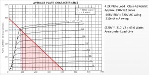
Basically with 4.2K load.... You hit the 0-BIAS curve at 88V plate and 310mA intersection ...This is with 390V on the screen...
So the delta plate voltage swing is 320V AC with respect to your 408V
The delta current swing is 310mA AC swing...
This give you 49.6 Watts area under this load line...
If your 8 Ohm load is mis-connected to the 4 Ohm tap you would have 8.4K load and the power output would significantly drop about where you at..
If you were to have the 8 Ohm load on the 4 Ohm tap, then would explain everything ....
Confirm the signal into the 6l6 grids are not clipping... Also confirm the plate load by doing a AC voltage ratio test of the OT...
Basically with 4.2K load.... You hit the 0-BIAS curve at 88V plate and 310mA intersection ...This is with 390V on the screen...
So the delta plate voltage swing is 320V AC with respect to your 408V
The delta current swing is 310mA AC swing...
This give you 49.6 Watts area under this load line...
If your 8 Ohm load is mis-connected to the 4 Ohm tap you would have 8.4K load and the power output would significantly drop about where you at..
Last edited:
Grid leak resistors on the OP stage, seem a bit high too, not checked the datasheet for 6L6GC in fixed bias but would suspect it to be lower than 220k. Try 47k - 100k and try reducing G2 R's to 100r also.
This is just tweaking though, measure the OP of each stage at full whack to make sure your getting enough IP to g1 - g1 of the 6L6's in open loop.
Andy.
This is just tweaking though, measure the OP of each stage at full whack to make sure your getting enough IP to g1 - g1 of the 6L6's in open loop.
Andy.
What are the equations to use to tell this? Doesn't it rely on the impedance of the OT? I would think that there's many Va values that could get 50W...but then again I'm the guy only getting 30W, lol.
The information is posted in the RCA Receiving Tubes Handbook.
And of course, ideal conditions are needed, such as the proper output transformer, etc.
I designed and built a 50W tube power amp based around a pair of 6L6GC...
Designing a tube amplifier would be good to start with the published tube data.
At the page 2 of the attached data you can find the conditions of PP amplifier at AB1 with fixed bias.
According to the tube manufacturer, 55 W out require 450 V plate voltage and 5k6 as load impedance.
Attachments
Designing a tube amplifier would be good to start with the published tube data.
At the page 2 of the attached data you can find the conditions of PP amplifier at AB1 with fixed bias.
According to the tube manufacturer, 55 W out require 450 V plate voltage and 5k6 as load impedance.
That is just one set of data points...
A quick and dirty way to get Push-Pull output power without resorting to doing composite curves is attached and is set up for the OP values...
Power Output is AREA under the curve when integrated...
Attachments
For the benefit of the OP, the class B PP load line slope is one quarter of the Primary plate to plate impedance.
Yes... P-P Class B is 1/4 Plate load.... since one tube at a time is active..thus source impedance is just the plate resistance of one valve..
P-P Class A is both tubes conducting therefore the source impedance is 2 tubes in series since there is a 0 net current in the Center-Tap, thus 180 degree AC currents.. The Valves see entire plate load...
Class AB gets wacky since it's a blend of both scenarios...
- Status
- This old topic is closed. If you want to reopen this topic, contact a moderator using the "Report Post" button.
- Home
- Amplifiers
- Tubes / Valves
- Can't get full power