Modern FFT distortion analyzers can reliably measure down to -120dB or so harmonics. They are limited to their own distortion (and to a lesser extent self-noise) in the measurement and A-D circuitry.
For instance, my AP SYS2722 has self-distortion of about -134dB 2nd harmonic. Suppose I measure my super-duper stuff and I measure -134dB 2nd.
What does that mean? Surely my super duper stuff does not have zero distortion, but it may be so low that it doesn't change the result.
Another possibility is that it is not very low at all but that the 2nd is in opposite phase to the analyzer own distortion, in such a way that the vector sum of the result comes out to -134dB. Is there a way to figure that out?
Let us say I do complex FFT in loopback and the result is L=a+bi. Then I do a complex FFT measurement of the DUT and the result is C=p+qi. Can I then say that the DUT distortion product is D=C-L=(p+qi)-(a+bi)=(p-a)+(q-b)i?
Jan
Last edited by a moderator:
Put a LPF behind your DUT. If your DUT does not introduce any distortion, only the fundamental will be rotated and the overall measured distortion will change only with respect to the attenuated fundamental. If your DUT (together with the generator) produces a distortion, it will be rotated/attenuated and the vector sum with ADC distortion (created by the fundamental) will be different. That is what I use for splitting the overall measured distortions into DAC and ADC components in the digital distortion compensation - replacing a voltage divider with LP filter producing exactly same level of fundamental must not bring up any (extra) distortions (to the extent allowed by physics and circuits quality).
The next step - compensate both sides to keep distortions of both sides below your DUT distortion. Unavailable for AP though...
The next step - compensate both sides to keep distortions of both sides below your DUT distortion. Unavailable for AP though...
Let us say I do complex FFT in loopback and the result is L=a+bi. Then I do a complex FFT measurement of the DUT and the result is C=p+qi. Can I then say that the DUT distortion product is D=C-L=(p+qi)-(a+bi)=(p-a)+(q-b)i?
I would agree that C = L + D (with C, L and D complex numbers). This should hold at least approximately (considering things like noise, imbalances in the DUT and loopback channels of test hardware, etc.). Therefore D = C - L.
If there is an easy test setup, I could try and do some tests with my RTX6001 + MATAA. Since the RTX is rather low distortion, the DUT would need to have low distortion, too. And the whole setup would need to be low noise and stuff. Can anyone think of an easy-peasy setup to test this?
You can always add any level of distortion on the output (generator) side if you have signal generation under control. Either using chebyshev polynomials (only level under control), or adding pregenerated higher harmonics sine (both level and phase under control). E.g. chebyshev method https://www.diyaudio.com/forums/equ...nsation-measurement-setup-24.html#post5832116
Put a LPF behind your DUT. If your DUT does not introduce any distortion, only the fundamental will be rotated and the overall measured distortion will change only with respect to the attenuated fundamental. If your DUT (together with the generator) produces a distortion, it will be rotated/attenuated and the vector sum with ADC distortion (created by the fundamental) will be different. That is what I use for splitting the overall measured distortions into DAC and ADC components in the digital distortion compensation - replacing a voltage divider with LP filter producing exactly same level of fundamental must not bring up any (extra) distortions (to the extent allowed by physics and circuits quality).
The next step - compensate both sides to keep distortions of both sides below your DUT distortion. Unavailable for AP though...
Thanks - I will read it a few more times to be sure I grok it fully ;-)
The precomp stuff is not available on the AP, I know. But if I have a complex FFT from both situations I should be able to write a simple macro that extracts that difference and plot it, no?
Jan
REW allows insertion of selected harmonics (2 to 9), with settable magnitude and phase, for its tone generator, along with bandwidth limiting and distortion component measurements of the loopback spectrum.
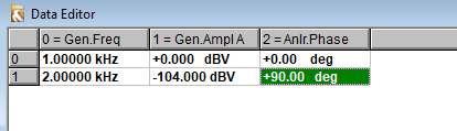
Using my EMU0404 USB as DUT with loopback, I have 0.0006% 2nd and THD at 389.6Hz test tone when limiting bandwidth to just include 2nd harmonic. I can then null that out (0.0001%) with -104dB of added 2nd H with 90 deg phase shift.
Using my EMU0404 USB as DUT with loopback, I have 0.0006% 2nd and THD at 389.6Hz test tone when limiting bandwidth to just include 2nd harmonic. I can then null that out (0.0001%) with -104dB of added 2nd H with 90 deg phase shift.
For playing with distortion measurements, effects of compensation on each side, comparing channel performance etc., you can use the distortion compensation tool. No hardware calibration adapter is required for joint-sides compensation (on either side), just simple loopback (w&w/o DUT). Single-tone, dual-tone distortion measurement/compensation.
I know I promised the pre-installed image, will do so in the coming weeks...
I know I promised the pre-installed image, will do so in the coming weeks...
Sure, what would you like?REW's distortions end at -120dB. Perhaps John could lower the limit, it may be a simple change.
REW allows insertion of selected harmonics (2 to 9), with settable magnitude and phase, for its tone generator, along with bandwidth limiting and distortion component measurements of the loopback spectrum.
Using my EMU0404 USB as DUT with loopback, I have 0.0006% 2nd and THD at 389.6Hz test tone when limiting bandwidth to just include 2nd harmonic. I can then null that out (0.0001%) with -104dB of added 2nd H with 90 deg phase shift.
I think the AP can do that too in the multitone generator. You can specify individual tones for amplitude and phase.
Need to check.
Edit: yes it can, see attached. Powerful!
Jan
Attachments
Last edited:
REW allows insertion of selected harmonics (2 to 9), with settable magnitude and phase, for its tone generator, along with bandwidth limiting and distortion component measurements of the loopback spectrum.
Using my EMU0404 USB as DUT with loopback, I have 0.0006% 2nd and THD at 389.6Hz test tone when limiting bandwidth to just include 2nd harmonic. I can then null that out (0.0001%) with -104dB of added 2nd H with 90 deg phase shift.
So how do you determine the phase of the harmonic wrt the fundamental? Take it from the complex FFT?
Jan
Powerful!
Honestly, considering the price tag - generating a multitone in software with any initial phase is trivial
")
Maybe keep in mind that a specific component of distortion, namely a particular harmonic, has been considered. It may not be possible for a simple summation to yield the results you describe. Can there be a destructive result? Inspection of computed results suggests no and it’s been about 30 years since I (briefly) looked at the math.
I would agree that C = L + D (with C, L and D complex numbers). This should hold at least approximately (considering things like noise, imbalances in the DUT and loopback channels of test hardware, etc.). Therefore D = C - L.
If there is an easy test setup, I could try and do some tests with my RTX6001 + MATAA. Since the RTX is rather low distortion, the DUT would need to have low distortion, too. And the whole setup would need to be low noise and stuff. Can anyone think of an easy-peasy setup to test this?
Can you use one channel of the RTX as measurement channel and the other as the test tone generator/DUT? What would happen if both channels had exactly the same distortion, would the result from this 'experiment' come out zero?
Jan
If I remember correctly, it is required to measuring equipment be atleast 10dB better than device under test in order to know exact parameters of DUT.
Citing AES17 standard:
Citing AES17 standard:
And 10dB is pretty close to 3 in ratio. However I'm not 100% sure where I heard that and it may be not a case with THD measurments.4.3.3 Unless otherwise specified, the equipment used for measurements in this standard shall have an accuracy
in the parameter being measured of at least 3 times better than the specification being verified.
And I am just last in a long row, with people like phoffmann being at the forefront.
There is a very big difference between the wide and deep knowledge/experience you have acquired throughout the many years vs. the very narrow specific focus I learned in the single year of my distortion project.
Can you use one channel of the RTX as measurement channel and the other as the test tone generator/DUT?
Not sure I understand this. Is "measurement channel" not the same as "test tone / DUT"? Did you mean "loopback" instead?
Anyways, the RTX works like a USB soundcard. It has two outputs and two inputs, and you can output whatever you like on each channel (ok, that depends on the software features, too). Same for the inputs.
What would happen if both channels had exactly the same distortion, would the result from this 'experiment' come out zero?
That depends on what the software does with the data. Most software will deconvolve the data recorded from the DUT and from the loopback channels. This will fix the timing of the measurement (like latency of the sound I/O of the computer) or the "linear distortion" (like non-flat frequency response of the test equipment). I don't think the deconvolution will fix non-linear distortion.
- Status
- This old topic is closed. If you want to reopen this topic, contact a moderator using the "Report Post" button.
- Home
- Design & Build
- Equipment & Tools
- Distortion analysis - a thought experiment