Apologies in advance if this was covered in a different thread.
I am trying to tame the pops when using a selector relay to switch between two audio inputs.
The problem I am looking to solve is that every time I switch the signal sources, I get the dreaded pops form the relay. This happens with no signal applied and even when the inputs are shorted with RCA caps. There is no coupling cap on either inputs.
I am using a fly-back diode (1N914) with a 10ohm series resistor right on the relay coil, but still no difference.
I also tried separating the coil supply and powered the relay via a 9v battery. That did not help either.
has anyone encountered this issue and resolved it. I am pulling hairs here trying to get rid of the pops. Any help would be much appreciated.
Thank you in advance,
Peter
Last edited:
From my experience that comes from Elektor preAmp designs :
Every time you switch between an input , you switch off the line output relay for a moment . That way , pops and clicks are surpressed to the next stage . (power amp or HP amp). Of course your line out should be DC free or there might be a pop too ...
Every time you switch between an input , you switch off the line output relay for a moment . That way , pops and clicks are surpressed to the next stage . (power amp or HP amp). Of course your line out should be DC free or there might be a pop too ...
Apologies in advance if this was covered in a different thread.
I am trying to tame the pops when using a selector relay to switch between two audio inputs.
The problem I am looking to solve is that every time I switch the signal sources, I get the dreaded pops form the relay. This happens with no signal applied and even when the inputs are shorted with RCA caps. There is no coupling cap on either inputs.
I am using a fly-back diode (1N914) with a 10ohm series resistor right on the relay coil, but still no difference.
I also tried separating the coil supply and powered the relay via a 9v battery. That did not help either.
This is the relay type I am using:
G6SK-2 DC12 Omron Electronics | Mouser
has anyone encountered this issue and resolved it. I am pulling hairs here trying to get rid of the pops. Any help would be much appreciated.
Thank you in advance,
Peter
Hi Peter
Contact- less methods of switching are what you need to resolve the issue.
Could you show the circuit? Are you switching grounds as well? It sounds like you have a DC imbalanced between the sources, but of course that should not happen with the inputs shorted?
one line is is directly coupled to the driver circuit input, with nothing in between but the relay contact, the other line has coupling caps and pots....but even after removing the caps and posts then shorting everything to ground from the input side, I do get the pops...no change
tried a resistor in series with the flyback diode and D+R across the coil, tried a resistor in series with the coil and flyback diode across the coil...no avail
Attachments
Last edited:
From my experience that comes from Elektor preAmp designs :
Every time you switch between an input , you switch off the line output relay for a moment . That way , pops and clicks are surpressed to the next stage . (power amp or HP amp). Of course your line out should be DC free or there might be a pop too ...
yes, I think that switching the line out would solve the issue, but it would mean adding to the circuit with some type of sequence timer, right?
To avoid switching pops you need to ensure that the inputs and output from the relay contacts are all at the same DC level. This usually means coupling caps and ground leak resistors need to be present.
I have tried ground leak resistors on both inputs. I will dig more into your suggestion.
Do you have more specifics or a reference circuit?
Hi Peter
Contact- less methods of switching are what you need to resolve the issue.
you mean some sort of an octocoupler? would you please elaborate?
will do+1 for post 4
Replace the 1N914, a small signal diode, with an 1N400x and do not use a resistor in series with the diode. E
Thank you All for the quick replies. This thing drives me bananas
I've used DC-coupled relay inputs for years now without issues, with no pops. Your source should have close to zero offset as far as possible.
The switch used is always MBB. You can't run away from that. The one time I had a deadline and only BBM available I put 1000uF caps on the relay coils to simulate a MBB action.
You will always need a pull-down resistor separately on each input, and do not make the mistake of switching grounds. That can be nasty.
If you like, you can use a small input series resistor and bounce the unused inputs to ground to reduce crosstalk from those inputs (note: tube output stages will NOT like this, and it increases the source resistance seen by the next stage - so it may be iffy with bipolar input stages). I don't usually do this anymore though, using brains and keeping unused sources powered off is a better bet.
It's just a timer thing you can do with an RC + transitors or go with a CMOS timer . When you switch you let the output relay break the connection for let's say 200 ms but the switch over of the input selector relays after 30 ms or so . The relays switches in 5 to 10 ms as the datasheet shows so well witin the 200 ms.
I haven't got the Elektor circuit to show , but I tested it when I built my preamp . I didn't use it because 1) every time I switch the input the output relay would switch too , which makes 2 mechanical loud clicks , which I don't like . 2) The little click on the output is so small and short that it doesn't bother me . When switching 2 sources with a signal on , you don't even notice .
I'm not switching grounds .
If you have an output C and resistor , you can also go another way , that is used by some audio manufacturers and that is to mute (short) the output with a transistor . Not elegant but effective ... but here too you need timing through RC or timer IC.
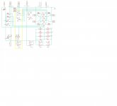
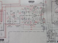
This is from a Sony DAT player :
I haven't got the Elektor circuit to show , but I tested it when I built my preamp . I didn't use it because 1) every time I switch the input the output relay would switch too , which makes 2 mechanical loud clicks , which I don't like . 2) The little click on the output is so small and short that it doesn't bother me . When switching 2 sources with a signal on , you don't even notice .
I'm not switching grounds .
If you have an output C and resistor , you can also go another way , that is used by some audio manufacturers and that is to mute (short) the output with a transistor . Not elegant but effective ... but here too you need timing through RC or timer IC.
This is from a Sony DAT player :
Attachments
Last edited:
I've used DC-coupled relay inputs for years now without issues, with no pops. Your source should have close to zero offset as far as possible.
The switch used is always MBB. You can't run away from that. The one time I had a deadline and only BBM available I put 1000uF caps on the relay coils to simulate a MBB action.
You will always need a pull-down resistor separately on each input, and do not make the mistake of switching grounds. That can be nasty.
If you like, you can use a small input series resistor and bounce the unused inputs to ground to reduce crosstalk from those inputs (note: tube output stages will NOT like this, and it increases the source resistance seen by the next stage - so it may be iffy with bipolar input stages). I don't usually do this anymore though, using brains and keeping unused sources powered off is a better bet.
tried with both sources shorted to ground.
added pull-down resistors for both inputs.
do you mean an analog MBB? have a part number?
do you have a circuit you I could reference?
Many thanks!
I have tried ground leak resistors on both inputs. I will dig more into your suggestion.
Do you have more specifics or a reference circuit?
You need a ground leak resistor on both sides of the relay.
I use line level relays extensively. Here's what I use. D3002 TE Connectivity / P&B | Mouser
I use them to switch capacitors in active filters as well as for line level switching. Properly configured, the switching is 100% seamless.
You need a ground leak resistor on both sides of the relay.
I use line level relays extensively. Here's what I use. D3002 TE Connectivity / P&B | Mouser
I use them to switch capacitors in active filters as well as for line level switching. Properly configured, the switching is 100% seamless.
will start with ground leak resistors and order some of the relays you suggested
thanks!
will start with ground leak resistors and order some of the relays you suggested
thanks!
Ground leak resistors should be as large as possible. Example if input impedance is 47K you could use 470K leak down resistor.
If you make it too big, it will take a long time to pull down the capacitor. 470K is fine for say a 2.2 uF coupling cap.
For active filter circuits, you can go even bigger. It depends on the values of the capacitors and resistors in the circuit. Example if the largest resistor in the circuit is 100K then by the "rule of tens" you might choose a 1 meg pull down resistor. But even this value might significantly alter the transfer function of the circuit. However the capacitor values are typically smaller in such a circuit than coupling caps. Say you're switching between a 0.1 uF and a 0.068 uF capacitor. With these values a 2 to 5 meg pull down resistor will be fine, and will not change the circuit operation in any significant way.
Also it isn't a good idea to switch direct coupled audio circuits unless you have the offset very low and stable. A pull down resistor won't help you here.
Last edited:
There are several ways a relay can inject switching noise into the signal. Here's my analysis:
Firstly if the signal is high impedance you may have capacitive coupling from the coil direct to the contacts or pcb. Solution is switch at a low impedance part of the circuit (opamp outputs), or slew-rate limit the voltage waveform going to the coil with a snubber circuit, and use groundplane.
Secondly the magnetic field from the relay coil may be cutting the signal path on the PCB, inducing voltages into them. Solution is reducing signal loop area on the PCB (slew-rate limiting is less likely to succeed as when the contacts snap together or apart the magnetic field changes rapidly even if the coil current is constant, as the magnetic circuit is mechanically changing?
In practice good layout, lowish impedance signals switched at line level shouldn't get too bad a click, but totally silent switching is unlikely to be possible with standard relays, they are not designed with magnetic and electrostatic shielding. Some experimentation would identify good and bad relays for these interference modes.
CMOS analog switch chips should be better, but you need to be careful to allow for the non-linearities of their on-resistance. Best to switch into a follower. Keep the digital logic traces away from the signals and over a digital groundplane. And usually you will be limited in headroom to the analog switch chip supply rails.
Hi Peter
Contact- less methods of switching are what you need to resolve the issue.
DC offsets will cause a pop regardless of the switching method.
G²
Agreed In a normal audio system there should not be DC present.DC offsets will cause a pop regardless of the switching method.
G²
If the contact is some how making noise due to opening and closing, a option is Optocoupling using a NSL32SR3 per audio channel, which neatly removes the contact in switches, due to its Resistance Off figure of 25M ohms.
https://lunainc.com/wp-content/uploads/2016/06/NSL-32SR3.pdf on the downside is 60 ohms when ON, but is usually not problematic.
- Status
- This old topic is closed. If you want to reopen this topic, contact a moderator using the "Report Post" button.
- Home
- Source & Line
- Analog Line Level
- relay as source selector - pop issues