Hi guys,
This may sound like a stupid question but to set the bias of an amplifier to 0 for adjusting would one increase the resistance or lower it?
I have mosfet amplifiers and transistor amplifiers and they all use 3 pin trimmers but on different sides of the board. Is it the same for both? The ones I've seen one pin in connected to another so only 2 of the pins actually give reading.
Most of my online searches are either for tubes or too difficult to understand. I assume its all the same for all technologies and it has to be set to 0 ohm.
Can someone with experience please shed some light on this? Its been on my mind for months
Thank you
Depends on the design and most allow adjustment within a range only, which might not include zero.If the pot is 100r I should increase it to 100r for 0 bias? Is that right for both channel? Thanks
It depends. Do you have a circuit diagram?I mean if the pot is X value should I increase the X value to maximum resistance for the value of the bias to be as low as possible?
I dont. I thought it was a general rule for all bias adjustments. I have been wondering about his for a long time.
I have had many different technology amplifiers and just wondered how could you without a circuit diagram safely reduce the bias to adjust it. Thats all. Its even keeping me up this late trying to figure it out
I have had many different technology amplifiers and just wondered how could you without a circuit diagram safely reduce the bias to adjust it. Thats all. Its even keeping me up this late trying to figure it out
I thought it was a general rule for all bias adjustments.
Depends on the particular circuit, it could be done either way.
It's more intuitive for clockwise rotation to increase the current.
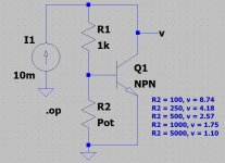
Attached is a typical Vbe multiplier. The pot (rheostat) is normally installed at location R2. As you can see, as the value of R2 increases, the voltage at v (the amount of bias) decreases.
If R2 would totally fail and become an open circuit, v becomes 0.93 volts.
But the pot *could* be installed at R1, or it could replace both R1 and R2 with the wiper on the transistor base. But what I posted seems to be the most common, and is fail-safe.
If R2 would totally fail and become an open circuit, v becomes 0.93 volts.
But the pot *could* be installed at R1, or it could replace both R1 and R2 with the wiper on the transistor base. But what I posted seems to be the most common, and is fail-safe.
Attachments
I always design my amps to work on clockwise to increase bias.
I always write on pcb next to pot "Start ACW" for start anti clockwise.
I put a resistor in series with the pot so the bias can never go infinite.
Added safety is a Zener across the bias circuit to stop high bias voltages.
I always write on pcb next to pot "Start ACW" for start anti clockwise.
I put a resistor in series with the pot so the bias can never go infinite.
Added safety is a Zener across the bias circuit to stop high bias voltages.
I would assume nothing unless the actual Bias circuit is drawn and posted here , period.
Please post amp schematic so we can suggest how to measure idle current .
If not possible, then do NOT mess with that amplifier.
You don´t even know what idle current you should set it to, nor any means to measure it, so only thing you can do is damage.
Expensive damage.
Don´t.I assume its all the same for all technologies and it has to be set to 0 ohm.
true, but does that apply here?A well designed amplifier will 'fail safe' if the adjustment pot opens up.
Not enough data to answer.If the pot is 100r I should increase it to 100r for 0 bias? Is that right for both channel?
Then you can NOT adjust bias, period.I can't measure current but can resistance.
Please post amp schematic so we can suggest how to measure idle current .
If not possible, then do NOT mess with that amplifier.
You don´t even know what idle current you should set it to, nor any means to measure it, so only thing you can do is damage.
Expensive damage.
If you don't have a circuit but you thought all Vbe multiplier circuits were the same, then I assume it's a commercial product that you are tinkering with so most likely, the direction is CW for increase and this would be specified in its service manual somewhere. So, what is the make/model?I dont. I thought it was a general rule for all bias adjustments.....
Alternatively, you could simply power up as presently set if you haven't changed every component in the amplifier already. Attach your multimeter leads securely across one of the large emitter (or source for mosfets) resistors connected to the output transistors. Using the lowest voltage range, adjust the pot. setting slightly while watching the change in the small voltage of only 5-30mV usually. Polarity is unimportant. This is the basic procedure for all bias current setting. You would then be certain which direction, either CW or CCW, was correct for minimum setting.
As the procedure will be detailed in the service manual, there is no cause for concern about reading mV instead of mA since the small voltage drop across the fixed resistor(s) is analogous to current, by Ohm's law.
Last edited:
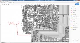
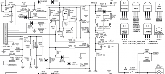
It's just as well that you told us the model because C300 is a mosfet type and this one has no source resistors from which to monitor the bias current anyway. The bias current is controlled by a separate, current regulated power supply and you'll have to assume that its adjustment is CW for increase, facing the top or front face of the pot. as shown on the larger attached diagram.
If you had no cause to adjust it, leave it set as it was previously, since this type of bias controller does not operate like the classic Vbe multiplier. Power up and the bias current will likely be close enough for safe operation as is. Then consider whether any adjustment is necessary.
If you had no cause to adjust it, leave it set as it was previously, since this type of bias controller does not operate like the classic Vbe multiplier. Power up and the bias current will likely be close enough for safe operation as is. Then consider whether any adjustment is necessary.
Attachments
It's just as well that you told us the model because C300 is a mosfet type and this one has no source resistors from which to monitor the bias current anyway. The bias current is controlled by a separate, current regulated power supply and you'll have to assume that its adjustment is CW for increase, facing the top or front face of the pot. as shown on the larger attached diagram.
.
When amps don't have emitter/source resistors they sometimes remove a fuse and measure the current across the fuse holder in one rail.
If I remember correctly the Maplin lateral mosfet amp was like as it had no source resistors.
That's true, Nigel. Here, NAD used a schottky/resistor combination in the positive supply rail for the purposes of both current sensing and providing test points. Attached is a snip of the amplifier output stage schematic for those with keener eyesight.
Attachments
Last edited:
You need to draw out the circuit around the bias pot and then it will be obvious which way the pot works.
A possibly dangerous way to do it is to set it half way and measure bias current and then turn pot each way to find which way is correct way to set it right.
- Status
- This old topic is closed. If you want to reopen this topic, contact a moderator using the "Report Post" button.
- Home
- Amplifiers
- Solid State
- resistors and Bias