So, here we go........
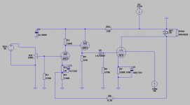
I have whats left of my brothers lost effort to build one of those chinese tube amps. I have the iron, 2-6n8p(6sl7), 2-6p3p(6l6). I've managed to surf the internet for seems like weeks to find one simple schematic using those exact valves. just wanting to throw this thing together for him so it isnt a total waste. please take a look at this drawing and lemme know what you think
FYI, this isnt my first one, Just my first with these valves. I have built amps from rescued console stereos before.
Thanks in advance
Attachments
")
Hi
Did a simulation on this - mostly concentrated on the output stage - not the driver. The cathode follower, as noted is not needed. The 100 ohm cathode resistor with the voltages shown results in about 70mA of cathode current (7V bias). The rating of the cathode resistor only needs to be 1W - actual dissipation about 0.5W.
Maximum input signal to the 6L6 is 14VPP - any more drives it into grid current on signal peaks resulting in clipping. With the 3500 ohm load shown, max power is about 3.4W. Raising the load to about 6500 - 7000 ohms will give about 5.1W with no sign of clipping. Slight non -linearity, but on my simulation I am not running any negative feedback. I have not done any distortion measurement but I think it would be pretty acceptable at that level, especially with the feedback active.
Thats my 2 cents worth.
Rob.
Alllensoncanon - not sure that you have a good understanding of how cathode bias works. When power is applied, the valve will start to draw current through the cathode resistor, and the cathode voltage will rise. As the grid is effectively grounded, the cathode voltage is the grid bias voltage. The cathode voltage (grid bias) will rise until an equilibrium point is reached - ie the tube current is the value supported by the value of the bias, ie cathode voltage. You can work out what values apply by looking at the transfer characteristic curves (if you can find a set of curves for these operating conditions) - ie plate current Vs grid bias. For 100 ohms, the current is about 70mA, corresponding to 7V bias.
I cant see how you can assume that 100 ohms will give you 100mA @ 10V bias. 10V bias actually occurs with a cathode resistor of 215 ohms, at a current of about 47mA. The quoted operating conditions in the Philips Miniwatt technical data book, 7th edition are for 250v on both plate and screen, with "approx"14V bias resulting in 72mA of plate current, and 6.5W of output power with a 2500 ohm load. Simulation with these parameters shows a slight variation, the bias value being closer to 12.5V for the other numbers to occur. I have had extensive experience in spice simulations, but not done much with valves. I don't know how accurate the model is or if it is for a slightly different variant of the 6L6 compared to the Philips data, but results are pretty close considering these unknowns.
You could certainly experiment with different bias and operating current values, but any improvement will likely also need a change in load impedance to fully optimise. Note that at 315V on the plate, it is probably easy to exceed the maximum plate dissipation - if you see it glowing red, back off a bit. Fortunately valves tolerate this abuse fairly well. I am yet to see a transistor that still worked after glowing red.
Will leave you with all these happy thoughts.
Regards
Rob
If you look at a 6L6 data sheet, at about 300V plate to cathode, Ip can be 100mA with a 10V bias. Of course G2 is 250Vfor the data sheet and the Ops intended to run G2 at 195V. Ip should be less if the tube he used is "typical" and he has good control of G2. If not, most likely, Ip will end up near 100mA. Another data point is look at other 6L6 push pull schematic. They use >200R or limit Ip to 60mA or so. As said, I would use 200R as the cathode bias resistor and push it up and down as needed.When power is applied, the valve will start to draw current through the cathode resistor, and the cathode voltage will rise. As the grid is effectively grounded, the cathode voltage is the grid bias voltage. The cathode voltage (grid bias) will rise until an equilibrium point is reached
Rob
Alllensoncanon
Your points noted. G2 voltage does make a big difference. I ran the original simulation with G2 at 190V as per the original posted schematic, raising G2 to 250V gets a lot closer to 100mA with 100 ohm cathode resistor. Also read through a lot of the posts on simulation models and it looks like the accuracy is not as good as I had expected - the simulation results seem to give current values that are lower than they should be for given bias figures. As I said, have a lot of spice simulation experience, but not with valves and was (un-realistically) expecting better accuracy.
At risk of being off topic on this thread - can you point me towards a good push pull 6L6 schematic? Searching this forum has not found much- new to the forum and not sure if I am using the search method correctly.
Regards
Rob
1. Use a 6L6GC. Its maximum plate dissipation is 30 Watts. A 6L6, 6L6G, 6L6GA, and 6L6GB all have maximum plate dissipation of only 19 Watts. 70mA and 300V plate to cathode is 21 Watts dissipation. Do not run your engine at 7,000 rpm all the time.
2. If you are going to parallel the input triode (and not using the cathode follower), you need to cut the cathode resistor value in 1/2, and cut the plate resistor in 1/2.
3. If you experience oscillations, try grid stopper resistors on each grid.
4. Do not forget, if the output transformer is connected out of phase, the negative feedback will actually be positive feedback, and you Will have an oscillator.
Happy Listening (report back the fun).
Last edited:
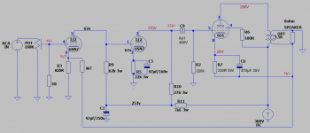
I wasnt very happy with the way the schematic posted turned out. I went with this one and like it a little better. Only issue i have is around 50% volume the sound starts to break up. I took some voltage readings while running the amp as noted on the schematic
Attachments
You have too much gain which is why you run into audible distortion at 50% volume. My guess is you are actually running into distortion way lower than 50% volume.
You only need to swing 20v peak to peak to drive a 6l6/6l6g in triode mode and I think you only need 30v on a 6l6gc. A single half of a 6sn7 will swing that much voltage if you have 2v rms input. If you have a weaker input, then a single 6sn7 can still work, but you would need to replace the plate resistor with a CCS or a plate choke.
I would either swap out the 6sn7 for a 6j5 or I would parallel the two halves of the 6sn7 and use a really basic CCS to load the tube. That way you take a whole tube out of the signal path which will give you less distortion.
How efficient are your loudspeakers? Do you have enough power and volume at 50% on the pot?
If you need a little more power, than try going from triode wired to Ultra Linear: If your output transformer primary has an Ultra Linear tap, you might try connecting the screen resistor, R6, from the screen to the ultra linear tap (disconnect R6 from the plate).
But now you will have way too much gain, just use one stage of the 6SN7 as was mentioned earlier: Disconnect pin 4 of the first 1/2 of the 6SN7, disconnect R9, and connect pin 1 to the 100k pot wiper. Keep C1. Change R5 from 22k to 1k Ohm.
- Status
- This old topic is closed. If you want to reopen this topic, contact a moderator using the "Report Post" button.
- Home
- Amplifiers
- Tubes / Valves
- 6SN7-6L6 valve amp