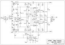
This is simplified version of my lateral mosfet amplifier here: https://www.diyaudio.com/forums/solid-state/243481-200w-mosfet-cfa-amp-118.html#post5297290
I think that to make it more simple would degrade this amp sound. Original amp is quite simple and sounds wonderfully, and I just replaced input stage CCS with resistor. THD increased a bit but not significantly.
Attached schematic, layout, some simulated plots and the gerber files.
I called it BSA, "Beautifully Simple Amplifier" or maybe "Best Sounding Amplifier".")
Have a nice bulding.
Damir
Corrections:
1. Some errors in 120W CFA lateral schematic and BOM, corrected here, post #85: https://www.diyaudio.com/forums/solid-state/338814-lateral-cfa-120w-bsa-9.html#post5831079
2. New improved PCB layout post #329. https://www.diyaudio.com/forums/solid-state/338814-lateral-cfa-120w-bsa-33.html#post6113290
I think that to make it more simple would degrade this amp sound. Original amp is quite simple and sounds wonderfully, and I just replaced input stage CCS with resistor. THD increased a bit but not significantly.
Attached schematic, layout, some simulated plots and the gerber files.
I called it BSA, "Beautifully Simple Amplifier" or maybe "Best Sounding Amplifier".
Have a nice bulding.
Damir
Corrections:
1. Some errors in 120W CFA lateral schematic and BOM, corrected here, post #85: https://www.diyaudio.com/forums/solid-state/338814-lateral-cfa-120w-bsa-9.html#post5831079
2. New improved PCB layout post #329. https://www.diyaudio.com/forums/solid-state/338814-lateral-cfa-120w-bsa-33.html#post6113290
Attachments
-
 120W-LMOSFET-VAS-OITPC-simple-sch.jpg293.3 KB · Views: 3,497
 -
120W-OITPC-LMOS-gerbers simple.zip88.2 KB · Views: 291
-
 120W-LMOSFET-VAS-OITPC-simple-FFT.jpg181.8 KB · Views: 2,887
 -
 120W-LMOSFET-VAS-OITPC-simple-CLG.jpg303.8 KB · Views: 2,587
 -
 120W-LMOSFET-VAS-OITPC-simple-LG.jpg301.2 KB · Views: 2,839
 -
 120W CFA lateral-simple-layout photo.jpg470 KB · Views: 3,397
 -
BOM 120W CFA lateral simple.txt1.6 KB · Views: 255
Last edited:
Good move Damir, an excellent simplification!!
Your son would approve - Birmingham Small Arms, a weapon manufacturer in Britain, who until about 1975 also produced some very nice motorcycles. I had one, a BSA 650, in the early seventies. Appalling distortion, but wonderful sound........ kept burning its exhaust valves.
HD
Your son would approve - Birmingham Small Arms, a weapon manufacturer in Britain, who until about 1975 also produced some very nice motorcycles. I had one, a BSA 650, in the early seventies. Appalling distortion, but wonderful sound........ kept burning its exhaust valves.
HD
Good move Damir, an excellent simplification!!
Your son would approve - Birmingham Small Arms, a weapon manufacturer in Britain, who until about 1975 also produced some very nice motorcycles. I had one, a BSA 650, in the early seventies. Appalling distortion, but wonderful sound........ kept burning its exhaust valves.
HD
Thanks Hugh.
My son still likes motorcycle, last one BMW, not sure what model. I am not very happy with this.
Best wishes,
Damir
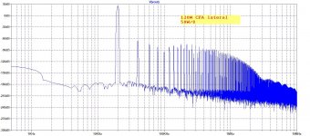
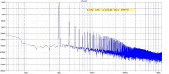
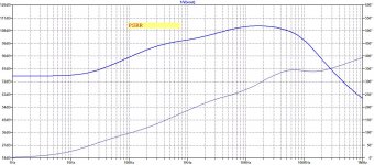
This is FFT at 20kHz, and it shows second harmonic on the same level as FFT for 1kHz at the same output power. This is result of flat Loop Gain up to 20kHz.
Might be to do with bias current not being enough ?
Might be to do with bias current not being enough ?
I don't get what you want to say? Bias current was set to 130mA per output pair.
This is FFT at 20kHz, and it shows second harmonic on the same level as FFT for 1kHz at the same output power. This is result of flat Loop Gain up to 20kHz.
Looks about 80db down to me, or am I missing something ?
Nigel,
I make it 66dB + 28dB = 94dB down for H2.
I have to say that this is exceptional. I normally see around 70dB down at 20Khz for H2. Bravo, Damir!
HD
And what is important too, it follows decreasing harmonic pattern similar to 1kHz FFT.
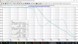
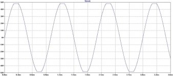
Here is clipping behavior.
Attachments
This is FFT at 20kHz, and it shows second harmonic on the same level as FFT for 1kHz at the same output power. This is result of flat Loop Gain up to 20kHz.
It's interesting how the loop gain is flat up to almost 20kHz (where my best CFA is only up to 1k). I looked at the cct to find out why it is so. I think it is from the extra 1 gain stage i don't have? But surprising to me is, my amp has better thd 1kHz AND 20kHz (at lower power, due to 36v supply), so I'm not quite sure if the 20kHz loop gain plays an important rule here?
Somebody mentioned that he is using compensation to tailor the harmonic spectrum of his amps. So i'm trying to figure out, what is the benefit of this extra complex compensation? Mine is stable with only one cap across Rfb. Your amp is more stable of course, but i predict that it is simply caused by the 47pf connected directly to the output.
Dear johnego,
Would you mind sharing more details about your amp like schematic ?
gannaji.
I'm sorry, gannaji, I'm not ready to share my findings in audio especially amplifier design, which can be seen from my amps.
I'm not ready to share my findings in audio especially amplifier design, which can be seen from my amps.
Hi Johnego,
May I ask what you have discovered so far ?
Jacques
Very interesting and tempting design.
Check your silkscreen, you have Q9 and Q5 at the same location with the actual Q5 marked elsewhere on the board. Again, very cool design, any chance you would provide some gerber files? Thanks
Edit: Totally missed you provided gerbers already - awesome and thanks!
Check your silkscreen, you have Q9 and Q5 at the same location with the actual Q5 marked elsewhere on the board. Again, very cool design, any chance you would provide some gerber files? Thanks
Edit: Totally missed you provided gerbers already - awesome and thanks!
Very interesting and tempting design.
Check your silkscreen, you have Q9 and Q5 at the same location with the actual Q5 marked elsewhere on the board. Again, very cool design, any chance you would provide some gerber files? Thanks
Edit: Totally missed you provided gerbers already - awesome and thanks!
Thanks, it slipped me, but not big error, just that one is Q9.
Yes the gerbers are for anyone to use, just not for commercial.
I'm sorry, gannaji, I'm not ready to share my findings in audio especially amplifier design, which can be seen from my amps.
At least, will you kindly desist from making comparisons to your amps, whose details are not available ? Else, no meaningful discussion can take place.
Last edited:
Hi Johnego,
May I ask what you have discovered so far ?
Jacques
Hi Jacques,
I'll try to answer you without polluting this thread. Please don't ask any detail
Many don't realize that electronics and audio is not the same entity. They have unconsciously assumed that whatever good electronically is good also for the sound. What i have been doing is correlating numbers with perceived sound, which to some extent, everybody do, i specifically do it in amp design, while searching for the best sounding amp, starting with one for each 'topology'. Easier for me because my ear is very sensitive.
In the process, I normally have built 'thresholds' for some parameters. I have also found my own practical methodology or design processes. It takes time to do this but i have done it everyday for so many years.
This is i believe similar to what AKSA did. He approved this new amp by Dadod but i believe not so with the 200W one. AKSA liked the resistor current source for the input, i think because this create the good sounding distortion spectrum, which is my favorite too. But i used ccs because (1) PSRR is rather insufficient (2) i assume the very low distortion might hide the effect of the slightly better distortion spectrum. But of course, i WILL try and compare, and this will add to my findings. But the biggest finding, i will not talk about it.
At least, will you kindly desist from making comparisons to your amps, whose details are not available ? Else, no meaningful discussion can take place.
You forget that some people with knowledge can read from less detail. I can show a schematic for example, and it is of no use to some because it will sound bad when hfe is below 500 but will sound good as i want it when hfe is above 700.
- Home
- Amplifiers
- Solid State
- Lateral CFA 120W - BSA