I have an inexpensive phono preamp here. The noise levels (hiss) were much too high, although it works perfectly well otherwise.
The original opamps were TL071, so as a first step, I replaced these with OPA134 opamps. The noise levels dropped, but not significantly. Since I had a couple in stock , I decided to try an LT1028 in the first stage. Noise level dropped substantially. So logically, I decided to try a LT1028 in the second stage. It is actually noisier in the second stage than the OPA134.
Why would the LT1028 be quieter in the first stage, but not the second, than the OPA134.
All of these were quieter than the TL071 BTW.
Attachments
Why would the LT1028 be quieter in the first stage, but not the second, than the OPA134.
Because of the current noise of lt1028 as the riaa network impedance is high.I suppose you notice better SNR with mc carts and lt1028 in the first stage while the second stage has a much higher source impedance.For mm cart opa134 in both the first and second stage should be better.With mc cart lt1028 in the first stage and opa134 in the second should be better.
Last edited:
Fleabay was your supplier perhaps .....
No.
Because of the current noise of lt1028 as the riaa network impedance is high.I suppose you notice better SNR with mc carts and lt1028 in the first stage while the second stage has a much higher source impedance.For mm cart opa134 in both the first and second stage should be better.With mc cart lt1028 in the first stage and opa134 in the second should be better.
I will have a look at that. I checked this using MC only up until now.
yeah, on paper and ...by opa132(2132...)Texas Instruments now has several very low noise and distortion , high GBW, FET opamps. opa134 is now so much surpassed ..
Texas Instruments now has several very low noise and distortion , high GBW, FET opamps. opa134 is now so much surpassed .. BJT opamps like the LT1028 aren't suitable unless working from a low impedance (< 1kOhm or so) on both(!) inputs.
Pretty used what I hand on hand.
I'll have a look for something more appropriate. The LT is too expensive anyway.
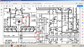
The inverting input has very low value resistors to ground. Would it be prudent to raise the value of these resistors to better match the non-inverting inputon both(!) inputs
Also would then the switching to change the gain be on the feedback resistor itself as opposed to the one going to ground. I realize that both will change the impedance of the inverting input, but would it make any difference to noise?
I can't do this preamp, but fro future reference.
ok no problem.
Looking at the values in dreamth's post, I really think they are at optimum as they are - LM49720/NE5532 type bipolar input opamps will give you as good a result as you are going to get given the source resistances.
The noise issue you experienced earlier after you swapped the opamps out may have been due to oscillation - I am not familiar with the TI OPA type devices, but looking at the 2nd opamp, I don't see any series resistor (typically 47 to 220 Ohms) in series with the output - this is required to isolate any cable capacitance. If you don't do this you can get instability problems arising from the cable/load capacitance.
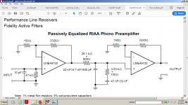
One thing you could do to try to quieten it down is raise the front end stage gain (is currently 23x) and reduce the 2nd stage gain (its also 23x thus the total gain at 1kHz is ~529) so the total input to output gain remains the same. So for example change the first stage gain 150 Ohm resistor to 75 Ohms (wire a second 150 Ohm in parallel with it) and increase the 2nd stage 150 Ohm to 300 (wire another 150 in series with it).
The passive EQ that sits between the two stages attenuates signals above 2120 Hz at 20 dB/decade. By putting the higher gain up front, you 'shift' some of the the noise behind the 2120 turnover frequency, and that will reduce your overall noise somewhat.
You will sacrifice 6 dB of overload with the above suggestion, but I doubt you will run into any problems.
These passive type RIAA EQ amplifiers can perform well, but ultimately they will always be outgunned on noise and overload by single stage all active circuits.
The main thing though is, have some fun
")
Looking at the values in dreamth's post, I really think they are at optimum as they are - LM49720/NE5532 type bipolar input opamps will give you as good a result as you are going to get given the source resistances.
The noise issue you experienced earlier after you swapped the opamps out may have been due to oscillation - I am not familiar with the TI OPA type devices, but looking at the 2nd opamp, I don't see any series resistor (typically 47 to 220 Ohms) in series with the output - this is required to isolate any cable capacitance. If you don't do this you can get instability problems arising from the cable/load capacitance.
One thing you could do to try to quieten it down is raise the front end stage gain (is currently 23x) and reduce the 2nd stage gain (its also 23x thus the total gain at 1kHz is ~529) so the total input to output gain remains the same. So for example change the first stage gain 150 Ohm resistor to 75 Ohms (wire a second 150 Ohm in parallel with it) and increase the 2nd stage 150 Ohm to 300 (wire another 150 in series with it).
The passive EQ that sits between the two stages attenuates signals above 2120 Hz at 20 dB/decade. By putting the higher gain up front, you 'shift' some of the the noise behind the 2120 turnover frequency, and that will reduce your overall noise somewhat.
You will sacrifice 6 dB of overload with the above suggestion, but I doubt you will run into any problems.
These passive type RIAA EQ amplifiers can perform well, but ultimately they will always be outgunned on noise and overload by single stage all active circuits.
The main thing though is, have some fun
The inverting input has very low value resistors to ground. Would it be prudent to raise the value of these resistors to better match the non-inverting input
Also would then the switching to change the gain be on the feedback resistor itself as opposed to the one going to ground. I realize that both will change the impedance of the inverting input, but would it make any difference to noise?
I can't do this preamp, but fro future reference.
For the second op-amp, you could connect an RC network that resembles the impedance of the passive correction filter in series with the negative input, or you could use a more suitable op-amp. The LT1028 is exceptionally bad regarding current noise with unequal impedances.
The LT1028 was an experiment, and obviously out. Since I don't want to change the circuit (not worth it in this case) I'm leaving the OPA134 there as it is fairly quiet there.
I am going to try Bonsai's idea and increase the first stage gain, and reduce the second. I've done this before and it works well.
Now I know the mechanism at work here, it's a matter of finding suitable opamps and a bit of tweaking of the feedback loop for optimum performance.
I am going to try Bonsai's idea and increase the first stage gain, and reduce the second. I've done this before and it works well.
Now I know the mechanism at work here, it's a matter of finding suitable opamps and a bit of tweaking of the feedback loop for optimum performance.
Under what conditions was the noise level observed? Shorted input, open input or include connectet cartridge ?I have an inexpensive phono preamp here. The noise levels (hiss) were much too high, although it works perfectly well otherwise.
The original opamps were TL071, so as a first step, I replaced these with OPA134 opamps. The noise levels dropped, but not significantly. Since I had a couple in stock , I decided to try an LT1028 in the first stage. Noise level dropped substantially. So logically, I decided to try a LT1028 in the second stage. It is actually noisier in the second stage than the OPA134.
Why would the LT1028 be quieter in the first stage, but not the second, than the OPA134.
All of these were quieter than the TL071 BTW.
Which cartridge was in use (MM mor MC) ?
Is there a significant difference include and exclude record surface noice ?
if the latter is the case, then everything else should be aimed for the best possible sound quality, but not for the lowest noise level.
Last edited:
I guess I should clarify a few things.
This is more of an exercise to find what is causing the noise and the mechanisms at work here. Not the first time I've come across gear that was noisier than they should be and have always found a way to quieten things down. I don't want tor re-design this product or make major changes.
Batteries are out. Besides the power supply is well regulated and filtered, in fact it will run for several minutes with power off (which doesn't affect the hiss)
There is no oscillation, and RIAA is surprisingly accurate.
What I'm finding is that it is current noise, and the impedance of the inputs seems to be fairly critical, although there is a broad range where there is no audible difference.
I've wondered in the past about a phono preamp I built several years ago. The first set of circuit boards were very quiet. I made some changes to the layout to better accommodate the chassis, and one channel had excessive noise, the other quiet.
The cure for this second set of boards was to cut the existing grounds and move them closer to a common point that was on the other channel. Both channels dead quiet.
I never did investigate the cause of this as the product was discontinued, and I went on to other things until this little preamp came across my bench.
So thanks for your responses, I now have some things to investigate.
Every device has both current and voltage noise. Which device performs best depends on the best match with the circuit impedance. In general, lower resistance means lower noise voltage, but you have loading to consider as well. Matching input resistors just adds more noise because the added resistor noise is not related to the existing noise, ie does not cancel.
In this circuit, the high frequency noise of the first stage is attenuated by the RIAA network, but not so for the second stage. So if the op-amp has high frequency noise, it works ok in the first stage but not in the second. Noise in the first stage at lower frequencies is amplified by the second stage, but not noise in the second stage.
So for the first stage you need to focus on the noise voltage and a low 1/f frequency, but just over-all noise in the second stage. You may want to use a bjt input op-amp for the first stage.
Last edited:
- Status
- This old topic is closed. If you want to reopen this topic, contact a moderator using the "Report Post" button.
- Home
- Source & Line
- Analogue Source
- Opamp Phono Noise