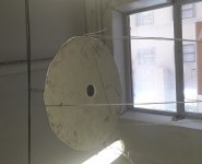
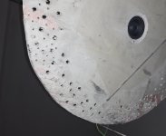
To enhance diffraction at the box edges, I cut a circular panel, the driver in the center.
The radius of the panel is 28cm
The mic is on axis, at 70cm from the driver.
The additional distance for the diffracted wave is 33cm in length, 1ms in time.
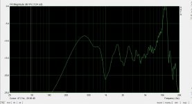
FR by a window 5ms
The radius of the panel is 28cm
The mic is on axis, at 70cm from the driver.
The additional distance for the diffracted wave is 33cm in length, 1ms in time.
FR by a window 5ms
Attachments
... and the panel thickness ...
Too many parameters for "build and measure".
The only reasoning I can do, is putting a mud pool on a wave step. Thus it loses step and power. Phase and width.
A node must meet a hole ...
But they also build micro-perforated panels. What kind of model do they have?
Too many parameters for "build and measure".
The only reasoning I can do, is putting a mud pool on a wave step. Thus it loses step and power. Phase and width.
A node must meet a hole ...
But they also build micro-perforated panels. What kind of model do they have?
Hi, thank you very much for your reply.
My goal is to find an alternative method to rounded edges, possibly more effective in diffusion.
Looking around, I found expressions for the acoustic impedance of a hole. They consider a random acoustic field, and place holes with a random criterion.
In the specific case of box edges, direction (parallel) and position (distance from the driver), they have no freedom.
I'm looking for what this implies.
Very interesting!
Yes with holes you can make a gradient in the acoustic impedance of the round baffle. Your simple setup is proof of concept.
Some quick thoughts:
The thinner the baffle, the more effective the holes will be.
Baffle vibrations can become audible.
In theory you can eliminate diffraction completely.
In practice, I think, you must be able to get good results.
Decrypting this paper. It seems to me that the holes I can produce, diameter / length ratio close to 1, mix absorption and diffusion.
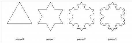
A fractal shape of the edges would seem useful, if translated into a similar dispersion of the holes.
But I distrust what seems useful to me: when I tried to diffuse by spheres, I built a powerful acoustic lens.
A fractal shape of the edges would seem useful, if translated into a similar dispersion of the holes.
But I distrust what seems useful to me: when I tried to diffuse by spheres, I built a powerful acoustic lens.
Attachments
Did you try eccentric mounting i.e same diameter but mounted significantly off center.
Some speaker companies (e.g. Wilson Audio) have felt around their tweeter often with a star pattern which could work not only as an absorber (at high frequencies) but also via diffraction.
Some speaker companies (e.g. Wilson Audio) have felt around their tweeter often with a star pattern which could work not only as an absorber (at high frequencies) but also via diffraction.
I hope someone signals my foolishness if excessive.
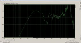
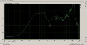
Looking at the images in #1 and #2, it seems to me that the holes D10 produce a semi-transparent panel around 1 KHz. The 1KHz dip decreases, and moves to 1.3KHz, as if I had cut off the edge. Resistive behavior.
Instead some emission seems to happen above 4KHz.
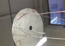
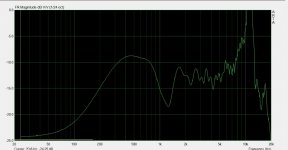
So, I produced 4mm holes in the outer ring:
Looking at the images in #1 and #2, it seems to me that the holes D10 produce a semi-transparent panel around 1 KHz. The 1KHz dip decreases, and moves to 1.3KHz, as if I had cut off the edge. Resistive behavior.
Instead some emission seems to happen above 4KHz.
So, I produced 4mm holes in the outer ring:
Attachments
Last edited:
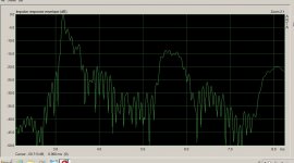
Each hole should acts as a resonator and its resonance frequencies would be dependent on diameter. The varying distance of the holes from the driver should generate different time delays and therefore different comb filter effects (compared to the edge).
I wonder how the impulse response of your different versions looks like.
I wonder how the impulse response of your different versions looks like.
Last edited:
Yes, I think so: they are resonators.
But everything happens in a 8cm wide band, I think that phase plays the role: the balancing of different holes could decrease combness.
I am not able to read IR, I will provide it with the next measure, but I would need help setting the window.
However, I have not seen elongations.
But everything happens in a 8cm wide band, I think that phase plays the role: the balancing of different holes could decrease combness.
I am not able to read IR, I will provide it with the next measure, but I would need help setting the window.
However, I have not seen elongations.
Are you familiar with Binary Amplitude Diffusion panels? It looks like you're trying to do something similar to that. The hole patterns can be calculated. If you want to just generally reduce diffraction/combing you want to be semi random in an intentional way (pseudorandom). Just randomly drilling various sized holes is going to give you random results. I recommend doing some reading on calculating patterns for diffusion. Some terms to look up: Binary Diffuser, Maximum Length Sequence, Cox and D'antonio (the experts on diffusion and resonance. Wrote the best book on it), Amplitude grating diffuser.
I'm interested in them, not entirely familiar.
I found, by D'Antonio: US5817992A - Planar binary amplitude diffusor
- Google Patents.
The greatest effort there is to establish sequences more random than the random itself. And avoid the usual coincidences.
There is not much about holes.
Calculators for perforated panels, use derivations of the usual Helmholtz formula, with cavities. I do not find much on perforated panels in free space.
But now I do not need it.
It seems to me that in my setup, holes from 2mm up to 10mm, give what is required, from 0.8 to 8KHz.
I think it's "Acoustic Absorbers and Diffusers: Theory, Design and Application", 2009 Trevor J. Cox, Peter D'Antonio....
Cox and D'antonio wrote the best book on it
...
Thank you
I'm interested in them, not entirely familiar.
I found, by D'Antonio: US5817992A - Planar binary amplitude diffusor
- Google Patents.
The greatest effort there is to establish sequences more random than the random itself. And avoid the usual coincidences.
There is not much about holes.
Calculators for perforated panels, use derivations of the usual Helmholtz formula, with cavities. I do not find much on perforated panels in free space.
But now I do not need it.
It seems to me that in my setup, holes from 2mm up to 10mm, give what is required, from 0.8 to 8KHz.
@bicicletta: If you intend to DIY some of RPGs BAD panels, RPGs curved BADs show in their own measurements quite a bit of improved performance compared to the flat BAD and they are just as easy to DIY. (Easy is not equivalent to quick or not tedious work though.) You get a good curvature if a drilled panel is squeesed in place between 2 side ”bars” which have a distance apart of 94-95% of the flat panels width. Another more mproved and later BAD version is RPGs ternary BAD which introduces a -1 besides the ”usual binary” 0 and 1 as shown in the patent.
If you go for curved BADs, it would be a good idea to go for 3/8” (10 mm) holes instead of 1/2” (12,7 mm) and use masonite or thin plywood instead of MDF which is weaker and may crack when bent. Smaller holes means scattering/diffusion will go up in frequency and if you adhere the panel to an air tight box frame that its low frequency absorbtion will improve (as it it will then work as a Helmholtz absorber as well)
When I made my BADs several years ago, I wrote an excel spread sheet to ”customize” panel sizes, grid size and hole dimeters to suit my room. (Link to spread sheet: Gearslutz - View Single Post - RPG Bad Panel -- Detailed Plans )
Preparation for curved ternary BADS with some reflecting ”Chinese hats” acting as -1 behind the panel instead of insulation only

Side walls with curved ternary BADs, panel in place. 4x2 BAD units placed on 1 regular sized 48" x 96" plywood sheet

The back of the room with 2 flat BADs and a curved one.

Last edited:
- Status
- This old topic is closed. If you want to reopen this topic, contact a moderator using the "Report Post" button.
- Home
- General Interest
- Room Acoustics & Mods
- An attempt to diffuse really close to the source