After much thought and consideration i have decided to go ahead with the Alpair 10p.
I really want to do something like this:
TLb -- Table of Contents
Run a couple per side in a transmission line bipole. Should i run the rear one full or throw an inductor on it? I assume the size of the inductor will be relative to the size of the baffle? How does one calculate this in a bipole configuration?
Thoughts on this design?
Thank you!
Good gosh that takes me back, the project page was I think much earlier than the 2007 date listed in the edit, and I’m sure if any actually got built? The bipole configuration is something that Dave has played with many times since, and I’ve built at least 6 of the numerous designs - almost of which were for smaller diameter fullrangers, 4” mid-bass , or 6 - 8” woofers. My favorite ended up being a variation with one driver top mounted at an angle at the sealed end of the line - i.e. the Castle Microtower.
Personally I consider a single A10P quite capable by itself but Dave might have already considered revisiting this particular topology, although I’d suspect it might include one of the smaller Alpair metal cone models - such as Alpair5.2 - rather than a soft dome, and active bi-amping.
Personally I consider a single A10P quite capable by itself but Dave might have already considered revisiting this particular topology, although I’d suspect it might include one of the smaller Alpair metal cone models - such as Alpair5.2 - rather than a soft dome, and active bi-amping.
I have built several bipolar MLTL speakers which have been documented here on diyaudio. One design featured CSS FR125S and WR125S drivers. As with any bipole you have wrap effects around the cabinet which cause a resonance dip in the forward radiation pattern near frequencies which are half wavelength apart. In my case a 5-6 dB dip showed up about 400-500 Hz. You can mitigate that dip by rolling off the rear driver of the pair before the resonance frequency.
For details see:
Bipolar MLTL Speaker with FR125S/WR125S
Another dipole design had the drivers offset in an attempt to better address the wrap around resonance and to better disperse in-room effects. My design had the drivers spaced high and low in their front to back baffles. This approach will yield results akin to the castle arrangement suggested by Chris.
Offset Bipolar MLTL with CSS EL70 Drivers--Part 1
I like dipoles as they effectively double the in-room bass output of a speaker.
Last edited:
I am just trying to figure a way of keeping up the sensitivity of the A10P and doing away with a BSC.
The bipole transmission line configuration looked interesting especially with its relatively simple enclosure design and pretty good performance.
I was just wondering where to roll off the rear driver and how would that interact with the response of the transmission line... it at all.
or should I forget this method and just go with a simple BR A10P with a BSC?
Thanks!
Last edited:
AudioGeek,
The bipole configuration would naturally address the BSC if you view the polar plots of a bipole speaker. A bipole configuration radiates the same amount energy into the forward 180 degrees and the rear 180 degrees. Hence, it would work best away from the wall behind the speaker-- say 4-6 feet space spacing from the wall.
The wrap around effect needs to be taken into account if you wish and I have included how to take do that in my second link above. Assuming that you have connected the two drivers in parallel and have a 4 ohms overall impedance (two 8 ohms drivers in parallel for lower frequencies). The connection for a bipole speaker with the wraparound mitigation is for the rear driver to have the inductor inserted in series with that driver. Thus it would have an 4 ohms impedance for the bass/low mid area and transition to an 8 ohms speaker impedance as the wraparound inductor takes effect and chokes off the rear driver.
Now another way to go for BSC with two drivers in the box is to use a 1.5 way arrangement (see photo below) and connect such as I did for my two TangBand 3.5" drivers. Essentially, the two drivers are placed on the front baffle and electrically connected such that they both radiate forward for their bass frequency area. For the bass range the two drivers are essentially connected in parallel. One driver--say the lower front driver--with a series inductor connected in series similar to the bipole configuration so that the lower front driver rolls off at the BSC corner frequency point. Hence, you get the bass enhancement for the two drivers at low frequencies yet the upper driver radiates full frequency. The impedance goes from 4 ohms for bass and increases to 8 ohms for the upper frequencies.
http://www.patcave.com/diy2002/sjgc6958.jpg
Finally, if you go with the transmission line approach for two drivers I would go with a Martin King based MLTL design for the two drivers A10p vs. the older transmission line approach you mentioned in Post #1. Several A10p MLTL design are listed in the diyaudio forum.
Jim
Last edited:
+1 to Jim’s recommendation for an MJK worksheet calculated design, MLTL or otherwise. If your budget can afford dual drivers per side, I wouldn’t be surprised if Dave/Scott didn’t already have something sketched out with 2 front facing A10Ps - there was certainly something like that for the A7.3.
Frankly, though I’ve never personally found a single A10P to be deficient in either sensitivity or LF extension in the enclosures I’ve used - Pensils and FHXL - but then I’m no longer running low powered tube amps, so the sensitivity is not an issue. Also, neither of my listening rooms are huge, and I’d long ago lowered my average listening levels to the mid 80s at most. The Woden Silbury is also worthy of consideration, but they are a more elaborate build, and certainly the opposite of a compact stand mount monitor.
Woden Design | Silbury
just a thought... A10P in a BIB?
Given the depth and quantity of bass from a 10p in the FHXL enclosure, a BIB may be redundant, unless you have specific requirements, or just like to experiment.
jeff
We have had a lot of practise with bipoles since the TLb. With a FR the need for tweeters is eliminated.
For the A10p in a bipole one’s 1st thots go to a Pensil derivative. But i expect it might be too large. Here a quick sketch:
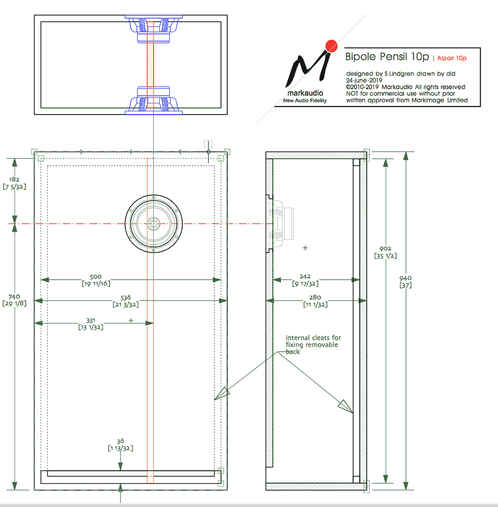
Probably more practical to double Jim’s A10p ML-TL. As thorough as the TLb artcle is it did not reveal the bipole dip. Making the box wider than deep helps minimize this.
If one finds the need to roll-off the back driver, an inductor in series if parallel connected, a shunt cap if connected in series. The choke-way will give an excess of in the bass, and is more critical to fine tuning. Which is best, if needed, depends on your room, room placement, taste, and the amp driving the speakers.
Another option is the castle “bipole” which has been shown to often be a better solution.
dave
For the A10p in a bipole one’s 1st thots go to a Pensil derivative. But i expect it might be too large. Here a quick sketch:
Probably more practical to double Jim’s A10p ML-TL. As thorough as the TLb artcle is it did not reveal the bipole dip. Making the box wider than deep helps minimize this.
If one finds the need to roll-off the back driver, an inductor in series if parallel connected, a shunt cap if connected in series. The choke-way will give an excess of in the bass, and is more critical to fine tuning. Which is best, if needed, depends on your room, room placement, taste, and the amp driving the speakers.
Another option is the castle “bipole” which has been shown to often be a better solution.
dave
Attachments
No. The bipole dip is the decrease in response caused by the phase difference at a frequency related to th edistance between the back driver, the front driver, and the shape of the box. It decreases as one moves off-axis such that when one is “looking” at the side, the dip goes away completely and the 2π>4π transition is perfectly dealt with (ignoring the room).
A sim (not mine)… IIRC the box x-setion is square.
Box dimensions can often be juggled to push the dip down into the region where room effects swamp.
dave
A sim (not mine)… IIRC the box x-setion is square.
Box dimensions can often be juggled to push the dip down into the region where room effects swamp.
dave
Attachments
Yes. Electro-acoustic modelsOK here goes, the dummy in the house is going to ask: is the bipole dip the flip side of the dipole peak the OB crowd is on about?
so i am nearly 100% certain that i will get the Alpair 10p. initially i am thinking of just making a set of stand mounted BR. Just one driver per side.
will be cheaper and easier to build for my first build with the Mark Audio drivers. Sorry to switch it around on everyone. question is though how to tune the BR enclosure? should i just do a standard flat frequency response tuning, or shelf it down a bit to allow for room gain... then how does BSC fit into all of this?
thank you for all your guys help!! promise i will actually build something here soon. lol
If you want simple http://wodendesign.com/downloads/simpleReflex-103-10p-plan-100214.pdf
I generally prefer the vent to be on the rear panel, but front is OK. Communication error on my part that wasn't really worth worrying about.
I generally prefer the vent to be on the rear panel, but front is OK. Communication error on my part that wasn't really worth worrying about.
BSC is room, room placement, taste dependent.
Here a slightly trickier box: https://frugal-phile.com/boxlib/P10free/fatCGR-MK10p-0v92-280418.pdf
dave
Here a slightly trickier box: https://frugal-phile.com/boxlib/P10free/fatCGR-MK10p-0v92-280418.pdf
dave
I’d suggest that whichever enclosure you finally settle on*, you first try them without any EQ- keeping in mind driver break-in, proximity to room boundaries, and amplifier damping factor & series R of speaker cabling are all contributing factors to whether /how much Baffle Step loss compensation might be required in your specific case.
*for those giving a flying eff, having many years ago made enclosures for specifically comparing the difference (with Fostex FE drivers at the time), I’ve always preferred the sound of high aspect ratio slot vents to simple round ports.
Of the dozens of enclosure types I’ve built over the past 20yrs, it’s probably no surprise that my favorites have all been from the Planet10 / Woden / Lindgren design catalogues - just none of them with round ports.
I see that Dave beat me to it, the enclosure he posted link to would be my suggestion as well- use BB or similar grade plywood
Last edited:
- Status
- This old topic is closed. If you want to reopen this topic, contact a moderator using the "Report Post" button.
- Home
- Loudspeakers
- Full Range
- Alpair 10p Build