Anyone know where I can find the First Watt (FW) schematic that allows channel separation via the filter caps?
Saw it somewhere in the middle of a thread.
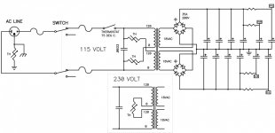
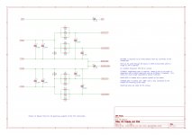
Looks almost exactly like the standard FW power supply, except a part of the supply rail is disconnected before the last reservoir cap.
Can anyone verify whether or not this version helps with channel separation or is it a "six or one half dozen" situation?
Thanks,
Vince
Saw it somewhere in the middle of a thread.
Looks almost exactly like the standard FW power supply, except a part of the supply rail is disconnected before the last reservoir cap.
Can anyone verify whether or not this version helps with channel separation or is it a "six or one half dozen" situation?
Thanks,
Vince

Hi Vince,
I've got a board design for that if you're interested.
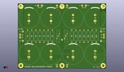
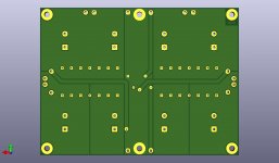
Mine uses 8 large caps instead of 12 smaller ones, and 12 Panasonic 3W resistors instead of 4 larger ones. It has holes for the line thermistor and a ground lift thermistor.
Boards just came back from Eurocircuits today, so I haven't tested them yet. But I'd be happy to post the Kicad files (or Gerbers) once I have if anyone is interested.
Cheers,
Jeff.
I've got a board design for that if you're interested.
Mine uses 8 large caps instead of 12 smaller ones, and 12 Panasonic 3W resistors instead of 4 larger ones. It has holes for the line thermistor and a ground lift thermistor.
Boards just came back from Eurocircuits today, so I haven't tested them yet. But I'd be happy to post the Kicad files (or Gerbers) once I have if anyone is interested.
Cheers,
Jeff.
Attachments
Anyone know where I can find the First Watt (FW) schematic that allows channel separation via the filter caps?
Vince
Erm... isn't the DIY shops' PCB 'breakable' into 2 discrete P Supplies ?
Just need to use 2 transformers
I do have 2 extra boards.
I had them done at Eurocircuits so they're high quality but also a bit on the dear side at €29/each. (€6 of that is VAT, so they might make more sense for someone in the EU, but I'm happy to send them anywhere.)
I'll stuff a board in the next couple of days and assuming it works put up the Kicad files and Gerbers.
Cheers,
Jeff.
Hi Vince,
I've got a board design for that if you're interested.
Hello Jeff, I believe there is a safety issue with your board if you intend to use mains on that PCB as is done in the FW commercial products There are regulations and you need to keep minimum distances between mains voltages and your secondary transformer voltages.... I believe it is about 5mm but am not sure. Be aware...
Folks:
For what little it's worth, I remember using that sort of power supply design years ago when I started modifying my old Bottlehead Foreplay. Bottlehead referred to it as a "pseudo-dual" power supply. In their design, there was a single transformer, a set of rectifiers and then a shared capacitor bank and then the channels separated with each channel having its own cap bank as a second stage. I had previously used a single shared power supply and recall that the pseudo-dual variation was noticeably better.
Fun stuff!
Regards,
Scott
I'll stuff a board in the next couple of days and assuming it works put up the Kicad files and Gerbers.
Cheers,
Jeff.
Hi Jeff,
I’d be interested in the Gerbers also.
What are the dimensions of your board? Thanks.
Regards,
Vunce
Hi Jeff,
thank you so much for posting here, I am also hugely interested in the Kicad design, as I postponed mine for more than a year now.
I'm also very happy that you used Kicad, as I wanted to try the new version 6 and set it up so that it works for me (and the audio stuff we all use.).
Thank you!
Matthias
- Home
- Amplifiers
- Pass Labs
- Alternate First Watt Power Supply Schematic