If you are after measuring the audio output voltage then there are a few things to be aware of...
1/ Audio is AC, not DC and so a simple meter on its own isn't going to work. At the very least you need some kind of rectifier such as a diode. That leads to another problem... sensitivity.
2/ Sensitivity. Even fairly loud audio wont involve much voltage. In practice that means a meter and rectifier wont even move until you turn the volume up a lot. Typically a meter would also need some means of 'holding' or 'stretching' the voltage for a little while so that the meter can respond to short peaks.
All easily do-able with a little electronics to drive the meter.
3/ The speaker outputs may not be ground referenced. You could find that the speaker is driven between two amplifiers (done to generate more voltage output) and so each speaker lead may be sat at some predetermined voltage... again easily solvable with a little electronics.
A meter, or any conceivable circuitry added to drive the meter would have no impact at all on the amplifiers output.
You are probably best looking around for ready made meter drive circuits (eBay etc) and adapting one of those.
Thank you for your reply.
I guess when I said voltmeter, I should have said multitester. There are several analog ones at the pawn shop up the street that nobody wants because they all use digital now. They measure ac voltage.
There is a guy locally selling a kenwood unit that is designed specifically for this, but its not inexpensive, and I would have to sell one of my amps to be able to afford it.
I would prefer to try and make something myself. There is a hobby shop near me that has an extensive supply of components. I really have no experience with this but can accomplish most things I try and learn.
Edit - And I assume that digital would not be good as the numbers would change so fast it would be impossible to read.
Last edited:
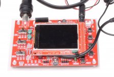
What about one the small oscilloscopes that aren't good for anything but audio?
You can get them fully assembled for $15, shipped. You'll need a 1x/10x scope probe but they're only about $5 each.
They are designed to operate off of 9v. A simple modification of changing the regulator can let them operate off of 12v safely.
This is a DSO138.
You can get them fully assembled for $15, shipped. You'll need a 1x/10x scope probe but they're only about $5 each.
They are designed to operate off of 9v. A simple modification of changing the regulator can let them operate off of 12v safely.
This is a DSO138.
Attachments
If you would consider an LED display, what about this Velleman kit?
Velleman K4305 Stereo Vu Meter Kit with 20 Leds, multicolored: Amazon.co.uk: DIY & Tools
Velleman K4305 Stereo Vu Meter Kit with 20 Leds, multicolored: Amazon.co.uk: DIY & Tools
If you can get hold of one then a 7809 is all you need. The more common 7805 would work if you added a series connected Zener into the pin 2 connection. The Zener voltage adds to the 5 volts... so a 3v9 or 4v7 Zener would be OK. Striped end of diode to pin 2.
Attachments
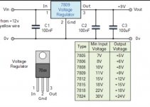
The problem with 12v is that the on board 5v regulator runs too hot. You can use an external 9v regulator in series with the power supply input to drop 12 to 9v to feed the input of the scope.
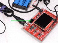
The one that was in the photo had the on-board to-92 case 5v regulator replaced with a TO-220 case 5v regulator. It's clamped to the board (with the appropriate insulators installed) with the black binder clip.
You could put the externally connected 9v regulator there as well.
The battery pack was used for the scope in the photo to isolate it from ground. This allowed it to be connected across the bridging terminals of an amp. Without it, you would only be able to connect to one bridged speaker output terminal at a time with the probe.
Attachments
Last edited:
The battery pack was used for the scope in the photo to isolate it from ground. This allowed it to be connected across the bridging terminals of an amp. Without it, you would only be able to connect to one bridged speaker output terminal at a time with the probe.
Maybe I'll run it off a 9v battery then. I don't understand why I couldn't measure both leads at once, but I'll just take your word for it because I have read a lot of your posts and know you are a knowledgeable person.
For most scopes, the probe tip is connected to a high impedance circuit. The ground, is... grounded (to the vehicle ground, if the scope is operating from the vehicle's 12v supply).
If you connect the ground of a scope to a speaker output terminal with signal, it's going to short that output to the vehicle ground and all sorts of bad things can happen.
If run from a battery, the ground of the scope is floating so connecting the scope ground to a speaker terminal that has signal doesn't short it to the vehicle ground.
You can still look at the signals from any channel when using the vehicle as the power source as long as you only use the tip of the probe to connect to the individual channels.
Running from a 9v battery works but will drain the battery in a relatively short time.
Pages 51 and 60 of my car audio site may help if you don't understand why there is signal on the negative terminal of a bridged output.
Does this look like the thing I need to run this off my car battery?
1, 3, 5, 10, 15, 20 pcs voltage regulator L7805 - L7815 ; LM 317 1.5A | eBay
1, 3, 5, 10, 15, 20 pcs voltage regulator L7805 - L7815 ; LM 317 1.5A | eBay
Don't buy semis from ebay. These may be OK but MANY are counterfeit or second rate.
That (LM317) is a 'programmable' regulator and while it will work, it needs additional parts to set the voltage.
The part you need to drop to 9v if you're going to do it that way (simplest) is an L7809. If you want to replace the regulator on board (slightly more difficult), you need an L7805.
Here's an example of the 7805 options. These are fully insulated to avoid the need for an insulator.
PMIC - Voltage Regulators - Linear | Integrated Circuits (ICs) | DigiKey
Last edited:
I'm kind of eager to solder on a board since I've never done it and its high on my bucket list. Are radio shack components any good? When they shut their stores here a hobby shop bought their inventory and is selling it close to where I live. I don't know if they have this exact thing, but it would be easy to check.
The regulators are dirt cheap so I'd suggest that you buy both (and extras). Use the 9v initially to get to learn to use the scope and if you decide you want to use it AND the scope is working properly, then replace the 5v on the board.
RS parts were somewhat hit and miss as far as quality is concerned. The regulators can be checked to see if they're close to their rated voltage before using them.
I'd suggest that you buy a small tube of heatsink compound if you don't have any and some sort of insulator (mica, etc) if you don't have anything on hand.
The compound is a white grease that's filled with a metal oxide (generally zinc). If you've ever replaced a processor in a computer, you likely have heatsink compound left over that you could use. You need only a tiny bit and none at all if you can find a sil-pad type insulator.
The 7809 doesn't need to be on a board. You can solder wires to the legs. 12v in, ground and output. You can solder the ground and output to the bottom of the white header on the scope if you don't have a plug. The ground would also go to the chassis of the vehicle.
You seemed to be concerned about cost so I'm trying to keep this as cheap as possible. You can buy plugs for this from ebay but you can also solder to the board.
The 78xx type regulators sometimes need a couple of small capacitors (0.1uF to 1uF) to make them behave but the capacitors on the board may be sufficient. That said, if the shop has a cheap assortment of small capacitors, buy them.
- Status
- This old topic is closed. If you want to reopen this topic, contact a moderator using the "Report Post" button.
- Home
- General Interest
- Car Audio
- Voltmeter load