I was making experiments with INA chips and I put together a relatively few components differential input phono with such. Thought I'd share. Because easy to configure I nicknamed it Chipomatic 
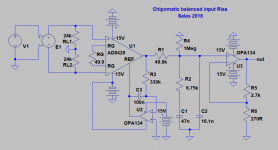
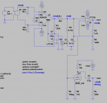
U1 is AD8429 which is a low noise instrumentation amplifier of very good general characteristics (SMD only). Texas INA217 (through hole) isn't a bad alternative by the way, it only gave ~2.5dB worse noise floor. U2 is a half OPA2134* configured as DC servo. R3 C3 values are chosen for a mild subsonic filtering effect. A passive RIAA equalizes the signal with 20dB loss which is gained back in U3 (the other OPA half) to drive some line preamp. U2 U3 could be done with singles too like the very good LT1792. Should always be a JFET input type due to the passive filter's high source impedance though.
RL1 RL2 are typically 48k total for MM cart or SUT but they would be optimum at 750R each for the AD's input current noise. When driven from say a DENON DL-110 of 160 Ohm source impedance, 1k each is doable for instance. Measuring 3dB better.
If the SUT has a middle tap on its secondary the GND point should be moved there than between RL1 RL2 to improve SNR due to less impedance for U1's input bias currents.
With the ~50R RG shown there's 42dB gain. Good for 2.5mV HMC. Adding 20dB voltage gain with a 10X step up transformer, or with an active differential pre-pre stage, its good for 0.25mV LMC. The graph's noise floor elevates 10dB in that case.
RG=63R gives 40dB gain and RG=100R 36dB gain for 3mV-5mV MM cartridges. 36dB & 10X SUT is good for 0.5mV MC. Output goal is about 300mV RMS nominal at 5cm/sec velocity with all types of cartridges and suitable gains.
I measured 28V pk-pk non clipped output at 1kHz with +/-15V rails thus 30dB overload margin above nominal output.
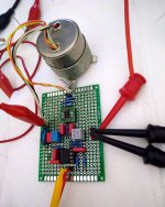
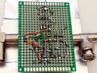
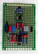
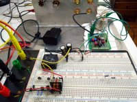
After breadboard phase I constructed a little matrix board monophonic example for 42dB. Its not best because it takes proper PCB of expert layout with ground plane and copper fill in such gains, especially for high performance chips, but its rather passable as proof of concept. To help against too much hum pick up I rested it on grounded metallized paper from a pack of cigarettes
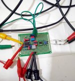
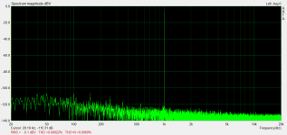
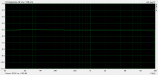
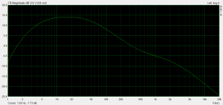
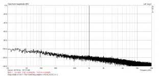
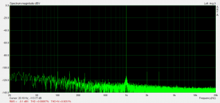
Anyways, I managed some FR & SPA measurements (using SE signal source and a balanced impedance divider). Showing its RIAA transfer curve, its conformity to flat with software anti-RIAA, and 1kHz 500mV RMS output level FFT for its THD. Also (added later) 1VRMS FFT at 62dB total gain by the addition of 20dB SUT when running on SMPS supplies to avoid mains interference spikes in the grass. Technically not too shabby results I would say. Given the configuration practicality and the matrix build I mean. Acoustically I don't know, I will have to either make yet another matrix channel or a decent printed board and listen to it some day in the near future to let you know. Hey I even have a tube output stage option designed already with 6DJ8 (E88CC) instead of U3
*Update: For U2 U3 servo & output dual op-amp I ended up preferring the AD823 (Through-Hole) and finally the OPA1656 (SMD).
U1 is AD8429 which is a low noise instrumentation amplifier of very good general characteristics (SMD only). Texas INA217 (through hole) isn't a bad alternative by the way, it only gave ~2.5dB worse noise floor. U2 is a half OPA2134* configured as DC servo. R3 C3 values are chosen for a mild subsonic filtering effect. A passive RIAA equalizes the signal with 20dB loss which is gained back in U3 (the other OPA half) to drive some line preamp. U2 U3 could be done with singles too like the very good LT1792. Should always be a JFET input type due to the passive filter's high source impedance though.
RL1 RL2 are typically 48k total for MM cart or SUT but they would be optimum at 750R each for the AD's input current noise. When driven from say a DENON DL-110 of 160 Ohm source impedance, 1k each is doable for instance. Measuring 3dB better.
If the SUT has a middle tap on its secondary the GND point should be moved there than between RL1 RL2 to improve SNR due to less impedance for U1's input bias currents.
With the ~50R RG shown there's 42dB gain. Good for 2.5mV HMC. Adding 20dB voltage gain with a 10X step up transformer, or with an active differential pre-pre stage, its good for 0.25mV LMC. The graph's noise floor elevates 10dB in that case.
RG=63R gives 40dB gain and RG=100R 36dB gain for 3mV-5mV MM cartridges. 36dB & 10X SUT is good for 0.5mV MC. Output goal is about 300mV RMS nominal at 5cm/sec velocity with all types of cartridges and suitable gains.
I measured 28V pk-pk non clipped output at 1kHz with +/-15V rails thus 30dB overload margin above nominal output.
After breadboard phase I constructed a little matrix board monophonic example for 42dB. Its not best because it takes proper PCB of expert layout with ground plane and copper fill in such gains, especially for high performance chips, but its rather passable as proof of concept. To help against too much hum pick up I rested it on grounded metallized paper from a pack of cigarettes
Anyways, I managed some FR & SPA measurements (using SE signal source and a balanced impedance divider). Showing its RIAA transfer curve, its conformity to flat with software anti-RIAA, and 1kHz 500mV RMS output level FFT for its THD. Also (added later) 1VRMS FFT at 62dB total gain by the addition of 20dB SUT when running on SMPS supplies to avoid mains interference spikes in the grass. Technically not too shabby results I would say. Given the configuration practicality and the matrix build I mean. Acoustically I don't know, I will have to either make yet another matrix channel or a decent printed board and listen to it some day in the near future to let you know. Hey I even have a tube output stage option designed already with 6DJ8 (E88CC) instead of U3
*Update: For U2 U3 servo & output dual op-amp I ended up preferring the AD823 (Through-Hole) and finally the OPA1656 (SMD).
Attachments
-
 CmaticTest2.jpg409.1 KB · Views: 579
 -
 CmaticTest.jpg428.8 KB · Views: 566
 -
 CmaticBAV.jpg497.4 KB · Views: 726
 -
 CmaticFRV.jpg429.4 KB · Views: 1,929
 -
 CmaticTHD.png21.8 KB · Views: 2,007
 -
 CmaticFR.png17 KB · Views: 1,972
 -
 CmaticRIAA.png19.9 KB · Views: 2,338
 -
 CmaticSCH.png17.9 KB · Views: 2,346
 -
 Cmatic2smps.jpg572.9 KB · Views: 732
 -
 Img.png55.8 KB · Views: 553
Have you got balanced output TT leads or balanced impedance SUT though? I don't know how those INA chips sound yet, just made it for technical practice. The FSP I am informed it will sound significantly better if with UltraBiB incorporated. A member reported that. Will have to revise it for V1.3 onboard shunts at a point.
Hi,
of course can it be wonderful.
Its almost a PlatINA, RG1, Calvin-Phono or one of the several other inkarnations of this theme, that mostly utilize a THAT or TI INA. ;-)
If You wanna know how those INA Phonos can sound ... just read one of the many threads or reviews of clearaudio balanced stages et al *lol*
jauu
Calvin
Another C O O L bit of solder slingin' !
.
Hi Salas
Nice bit of solder slingin'
Can I have some chips with that please.
One of the best things you can do with a turntable ...
... is to put some low-capacitance microphone-cable & nice gold-pinned XLR-plugs on it.
The only problem is ... then you can't plug it in to any of your kit.
I guess that's why you never see folks doing that.
Do I really want to plug my Thorens into my Stanton pro D.J. phono-amp/mixer though ? ...
... No !
Balanced is very tempting for the intrepid plastic-spinner !
But it seems that few take the plunge.
I'm surprissed that we haven't seen many balanced 'Simplistics'.
Merlin/Fellipes nice balanced 'Simplistic' was an inspiration to my u l t r a s l o w slingin'.
The circuit looks like a great one & simple as well.
Keep that junction-count L O W mmaann . . .
Go on folks ... Take the PLUNGE and hack oorrff those outmoded ancient RCA plugs.
You KNOW it makes perfect sense.
Si.
t.S.E.c
.
.
Hi Salas
Nice bit of solder slingin'
Can I have some chips with that please.
One of the best things you can do with a turntable ...
... is to put some low-capacitance microphone-cable & nice gold-pinned XLR-plugs on it.
The only problem is ... then you can't plug it in to any of your kit.
I guess that's why you never see folks doing that.
Do I really want to plug my Thorens into my Stanton pro D.J. phono-amp/mixer though ? ...
... No !
Balanced is very tempting for the intrepid plastic-spinner !
But it seems that few take the plunge.
I'm surprissed that we haven't seen many balanced 'Simplistics'.
Merlin/Fellipes nice balanced 'Simplistic' was an inspiration to my u l t r a s l o w slingin'.
The circuit looks like a great one & simple as well.
Keep that junction-count L O W mmaann . . .
Go on folks ... Take the PLUNGE and hack oorrff those outmoded ancient RCA plugs.
You KNOW it makes perfect sense.
Si.
t.S.E.c
.
Don't forget that MM cartridges have one pin connected to the case of the cartridge. To run balanced you need to ideally disconnect that and run a 5th wire, which puts a lot of people off balanced MM phono. I can live with that, but have transcended voltage amplifiers for my MM needs
Using shorter test cables and moving it about a bit cleans up further and the 50Hz hum spike is almost gone. Other related spikes probably from the lab supply's interference remain. I replaced the graph for 0.5V RMS THD in post#1. Interestingly at 1VRMS the second and third harmonic rise equally. Fortunately not only third for program peaks then.
Attachments
I was making experiments with INA chips and I put together a relatively few components differential input phono with such. Thought I'd share. Because easy to configure I nicknamed it Chipomatic
My goodness Salas does 8-legs, if you want to try a couple of gold plated DIP's just ask.
My goodness Salas does 8-legs, if you want to try a couple of gold plated DIP's just ask.
Thanks a lot Scott, but not to deprive your collection from rare packages. The SMT one works the same for home temperatures on the little adapter I think. Nice current feedback low noise instrumentation chip from Analog Devices BTW. Did you lend any ideas in its design?
I have made the Itch with valves, the FSP with JFETs, so a chips one was missing I guess
Thanks a lot Scott, but not to deprive your collection from rare packages. The SMT one works the same for home temperatures on the little adapter I think. Nice current feedback low noise instrumentation chip from Analog Devices BTW. Did you lend any ideas in its design?
No, just years of accumulated knowledge we all share.
I would be tempted to try something similar, with INA103, also 1nV/√Hz noise device, have a dozen lying around.
But, as stated, INA103 does not have the best noise performance with source impedances greater than 10K. On the other hand, should deliver “near theoretical noise performance” with source impendence around 200 Ohms. Sounds just right for MC input.
http://www.ti.com/lit/ds/symlink/ina103.pdf
But, as stated, INA103 does not have the best noise performance with source impedances greater than 10K. On the other hand, should deliver “near theoretical noise performance” with source impendence around 200 Ohms. Sounds just right for MC input.
http://www.ti.com/lit/ds/symlink/ina103.pdf
Or a THAT1512. MC carts are 40 Ohm or far below though and 1nV/rtHz can be acceptable to some but not SOTA as building a discrete headamp with Zetex minimal Rbb' transistors.
Depends on what is the interface. The AD8429 will be at its best with HMC or SUT or differential pre-pre with 100uF coupling caps.
Depends on what is the interface. The AD8429 will be at its best with HMC or SUT or differential pre-pre with 100uF coupling caps.
Don't forget that MM cartridges have one pin connected to the case of the cartridge. To run balanced you need to ideally disconnect that and run a 5th wire, which puts a lot of people off balanced MM phono. I can live with that, but have transcended voltage amplifiers for my MM needs
Alright, alright, I will add a BAL/SE input switch to a board layout so to can reconfigure the input side grounding at will. I tested it on the matrix example by moving the GND wire from between the RLs to -In and it works. The signal ground must no longer connect to the shielding paper for best hum result though. Only the mains earth from the lab PSU.
Or a THAT1512. MC carts are 40 Ohm or far below though and 1nV/rtHz can be acceptable to some but not SOTA as building a discrete headamp with Zetex minimal Rbb' transistors.
THAT has an in-amp building block that brings out enough pins to replace the input devices (actually use them as a cascode) with the Zetex devices or FET's for that matter. Unfortunately it only comes as a bumped die package.
Walt Jung and I published an AD624 based MM phono many years ago (I used it for years).
- Home
- Source & Line
- Analogue Source
- Chipomatic balanced input RIAA