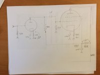
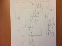
I wanted to show this to the community and see what people think. I got the schematic from jack at ElectraPrint. It is wired up and working on my bench as I type. I like the circuit because it is fairly simple.
What might you do differently.
TIA
Evan
What might you do differently.
TIA
Evan
Attachments
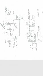
Jack is an extremely knowledgeable person when it comes to this subject (and if you can afford them I would not hesitate to order his transformers), so I'd be hesitant to change the schematic too much if he designed it. Looking at it, I don't see anything I don't like.
I am inclined to add a little negative feedback, however. I know this is viewed negatively by many, however it should improve the damping factor (worth it since you're running it as a pentode). Many people will disagree with me.
I am inclined to add a little negative feedback, however. I know this is viewed negatively by many, however it should improve the damping factor (worth it since you're running it as a pentode). Many people will disagree with me.
Jack is an extremely knowledgeable person when it comes to this subject (and if you can afford them I would not hesitate to order his transformers), so I'd be hesitant to change the schematic too much if he designed it. Looking at it, I don't see anything I don't like.
I am inclined to add a little negative feedback, however. I know this is viewed negatively by many, however it should improve the damping factor (worth it since you're running it as a pentode). Many people will disagree with me.
This circuit seems to have a few really bad design choices. No disrespect to op or Jack but this seems to break at least a couple common sense rules imjo and you are going to have some floppy bass with most speakers assuming you can keep 5u4s alive. Drop that 50r and reduce your first cap to 22uf for starters IMHO. But fixing the poor damping will require essentially a redesign of the front end to support the nfb you'll need to tame the df. Now if you are biamping and using this on the top end the df might not be as much of an issue.
Last edited:
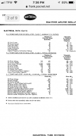
One thing I'm a little confused on is where that 20 watts is coming from. Looking at the 4D32 datasheet (no specs given for SE), it suggests a 3000 ohm P-P load for class AB1. I'm inclined to say that 5K is a little high... and I doubt you're making 20 Watts with those plate voltages.
Not that I'm necessarily the best person to ask, as I obviously missed a few glaring mistakes in my first post (capacitor voltage ratings...). Clearly I'm tired if I didn't notice that. Along those lines, to get the voltages in the schematic, that poor choke is dissipating 18 watts and dropping about 116 volts...
Also, is it just me or does a 4k plate resistor on that 6AN4 seem a tad low? It isn't a tube I'm real familiar with, but the datasheet I found doesn't list an anode load, and suggests a mu factor of 70.
Last edited:
No disrespect is implied and no offense taken. I asked.
I have stacked the first electrolytic caps and they are rated 500 volts so safely within their rating and half the capacitance. The rectifier is a 5u4gb.
I’m using a choke with less DCR so dropping less volts.
I appreciate the time and advice
Thanks
Evan
I have stacked the first electrolytic caps and they are rated 500 volts so safely within their rating and half the capacitance. The rectifier is a 5u4gb.
I’m using a choke with less DCR so dropping less volts.
I appreciate the time and advice
Thanks
Evan
Keep in mind that everyone has opinions on how they would do it, but everyone has a different application and different preferences.
If I were building it, I'd yard out that tube rectifier and go SS, double the filter cap sizes, redesign the front end using a different tube and load it full of negative feedback.
But I'm anything but a purist in this regard, and then you wouldn't even have the original circuit. Not everyone likes SS rectifiers and negative feedback.
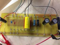
One other thing- It's hard to tell from the pictures, but if those big power resistors (chassis mount type) are the cheap stuff from eBay, I'd spring for some nice quality Dale resistors. Maybe I've just had a bad run, but my experience has been that they don't take surge current very well. I've had at least three go open almost instantly on startup with any decent size cap after them. PITA to track down because it's not like you expect them to go open.
If I were building it, I'd yard out that tube rectifier and go SS, double the filter cap sizes, redesign the front end using a different tube and load it full of negative feedback.
But I'm anything but a purist in this regard, and then you wouldn't even have the original circuit. Not everyone likes SS rectifiers and negative feedback.
One other thing- It's hard to tell from the pictures, but if those big power resistors (chassis mount type) are the cheap stuff from eBay, I'd spring for some nice quality Dale resistors. Maybe I've just had a bad run, but my experience has been that they don't take surge current very well. I've had at least three go open almost instantly on startup with any decent size cap after them. PITA to track down because it's not like you expect them to go open.
I modeled the power supply in PSUD II. I used 10 henry and 120 ohms for the choke. I assumed 2528 does not mean ohms or is a mistake. And I assumed 420 volts was an unloaded value for the transformer.
The data sheets suggest 250 volts in AB2 and 300 volts in AB1 on the screen of the 4D32 and 200 volts on the plate of the 6AN4.
With the stated assumptions the 4D32 plate supply is ~420v, Screen supply is ~260v and 6AN4 plate supply is ~200v.
These values match the operating point for the 6AN4 shown in the datasheet.
Steve
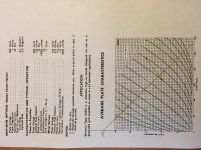
One thing I'm a little confused on is where that 20 watts is coming from...
It is easy to plot-out.
It does look like 14 Watts for 5K load. The 400V 120mA suggests 3.2k trial load which plots as 21+ Watts at clipping. THD will be high at this extreme swing; also clearly the data-sheet show-off Vg2 of 300V is too high for good linearity at this condition; these can be adjusted.
Attachments
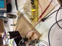
Good morning and happy thanksgiving to those who are celebrating. I have a few days off work and some time to play. I have done some thinking about the circuit and need some double checking of my conclusions.
It does seem that the anode load on the driver stage was quite low. At 4K ohms I was asking the driver to put out much more current then it wanted. I have changed to 10k and plotted the load line. If someone more experienced could check my plot it would be very much appreciated
Thanks
Evan
It does seem that the anode load on the driver stage was quite low. At 4K ohms I was asking the driver to put out much more current then it wanted. I have changed to 10k and plotted the load line. If someone more experienced could check my plot it would be very much appreciated
Thanks
Evan
Attachments
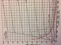
From yesterday to today I’ve plotted the operating conditions of my output tube and made some more a adjustments. With the original 90ohm cathode resistor on the output tube my whole circuit was drawing 220 mV at idle. With 28mV going to the front end and screen this left 192mV for the plate of the output tube. I adjusted the cathode resistor to 203ohm and now look to have 132 mA.
The red line on the graph is what I figured max plate dissipation is. I took 50 Watts from the data sheet and used ohms law to plot max current at plate voltage. I then plotted the dc load line and slid the line up near max dissipation.
There isn’t much resolution on the graph because I’m so squeezed up at the bottom but I’m wondering if I have plotted the max dissipation and quiescent operating point correctly.
TIA for taking a look
Evan
Attachments
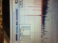
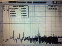
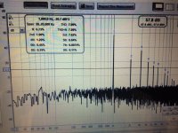
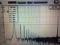
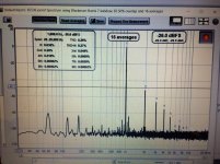
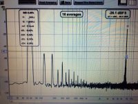
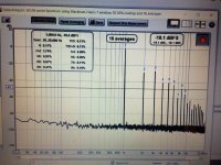
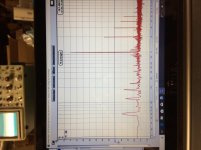
Thought I would report back with some data. I added potentiometers to the anode and cathode resistors on the driver, the cathode of the output tube and the grid leak resistor of the output tube. I also added a 4.7k grid stopper to the driver tube and a 1k to the output control grid.
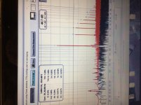
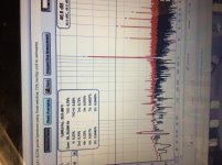
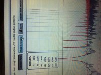
First photo is distortion at 1 watt before any tuning
Second photo is distortion again at 1 watt after some fiddling
Third photo is IMD at 1 watt
And fourth is distortion at clipping about 15 watts
The amp sounds nice playing on one of my efficient shop speakers.
Thanks
E
First photo is distortion at 1 watt before any tuning
Second photo is distortion again at 1 watt after some fiddling
Third photo is IMD at 1 watt
And fourth is distortion at clipping about 15 watts
The amp sounds nice playing on one of my efficient shop speakers.
Thanks
E
Attachments
AudioExpress April 2010 issue has an article on the construction of a triode strapped Class A2 SE using the 4D32. He used interstage and output transformers from Electra-Print.
http://thaihdbox.net/audioxpress/2010/04audioXpress_April2010.pdf
He went through 3 iterations of the driver stage before he was able to achieve 17 watts out of this tube.
Steve
http://thaihdbox.net/audioxpress/2010/04audioXpress_April2010.pdf
He went through 3 iterations of the driver stage before he was able to achieve 17 watts out of this tube.
Steve
Steve
Thanks for taking the time to respond. I have seen this article. I believe that jack recommended the schematic he did because of it's simplicity. He recognized my lack of experience and suggested something I could get my head around. I'm glad he did and do believe I am working it out.
I'm not sure what to expect with regards to distortion. The amp sounds good as it is. Jack has advised in an email that I should shoot for below 2% THD at a level I could use. If that is the criteria I'm there but with the amp just breadboarded now is the time to play. I did just try a 10m45 ccs as the anode load for the driver tube and gain went up as expected but so did distortion. I'll keep at it and report back.
Thanks,
Evan
The AudioExpress article about this tube caught my attention.
I acquired 8 4D32s this year and transformers with 3k and 5k impedances suitable for use with them. Like you, I want to try them in an SE amp. I asked Anatoliy (Wavebourn) for a few of his A2 driver boards for my experiments (he has a short thread for the boards).
I am looking forward to seeing your results.
Steve
A bit more adjustment has made some improvement. Both tubes are running within their max dissipation. But not by much.
B+ is at 450v with 274 volts going to the output tube screen grid and the input tube plate
Distortion and IMD at 1 watt and at clipping about 15 watts
I want to see if I can do something about the 60 hertz power line noise
B+ is at 450v with 274 volts going to the output tube screen grid and the input tube plate
Distortion and IMD at 1 watt and at clipping about 15 watts
I want to see if I can do something about the 60 hertz power line noise
Attachments
This is the amp wired in triode mode. I tied the screen grid to the anode of the output tube with a 100 ohm stopper. Distortion is lower and has a nicer distribution of harmonics. The downside is lower gain and clipping at about 8 watts.
First two at 1 watt and third at clipping 8 volts into 8 ohms
First two at 1 watt and third at clipping 8 volts into 8 ohms
Attachments
More measurements. I’ve changed to led bias on the input tube and fixed bias for the output tube. I have also added a mosfet source follow between the input and output tube. This didn’t effect distortion. I was hoping to be able to drive the output tube into A2 for more power output but it still looks to be copping at about 10 watts.
More to come
Thanks
Evan
More to come
Thanks
Evan
Attachments
- Status
- This old topic is closed. If you want to reopen this topic, contact a moderator using the "Report Post" button.
- Home
- Amplifiers
- Tubes / Valves
- New 4d32 SE project looking for critiques / advice