Hello Folks,
I was doing some distortion checks with my Amber analyzer and making adjustments as per the service manual for one of my tuners. I was able to adjust for minimum distortion levels as required but I have a hard time understanding the analog scale. The specs in the owners manual of most devices will indicate the percentage of distortion of the unit and I would like to be able interpret the percentage on my meter scale. My Amber meter does appear to be able to give me percentage on the scale as in the photos that I attached but I need help interpreting it.
The photos attached are of the actual reading I am getting after adjusting for the lowest level.
Can anybody tell me what percentage of distortion is being displayed and how do you read that with the pictures I attached?
Thanks!
Roland
Oh and I do have the manual for the Amber meter but it's pretty vague about reading the scale so I figure there might be some veterans here that could read those readings with ease.
Attachments
Last edited:
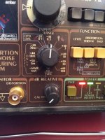
The bottom scale on your meter is for volts and percent. Your distortion range is currently set for -40dB or 1% range. If you look at the lower range on the meter you'll see one on the right hand side. That is the 1% mark. So you are showing .65% distortion on the meter or -44dB as Jan pointed out. The 0 directly above the 1 we just referenced is the -40dB point for the range you're currently on.
Once you get used to the meter and how it relates to what you're measuring you'll love it.
Once you get used to the meter and how it relates to what you're measuring you'll love it.
Thanks so much to all for the info!
So let's see if I understand correctly.....
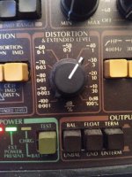
Lets say we use the 3rd photo and I set the knob for -20db/10%
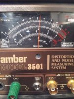
Would I be correct in saying that if we look at the 4th photo, that the 0 on the right side of the scale representing dbv would be equal to -20 db as reference and the actual reading would be -23.8db? and that the 1 on the volt/percent scale below it would represent 10 percent and the actual reading of the needle would be 6.5%?
So what would the lowest scale on the bottom represent?
While I was doing my alignment, the FM signal generator was set for 1khz . I measured the output voltage at the RCA jacks of my tuner with my volt meter and it was .289 V @ 1KHZ.
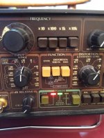
I adjusted the voltage input range knob as in the first photo accordingly. From what I seem to understand, the two red arrows that point left or right of the knob, light up to indicate if I need to turn the knob higher or lower based on the input voltage.
Does this seem to be a correct assessment?
So let's see if I understand correctly.....
Lets say we use the 3rd photo and I set the knob for -20db/10%
Would I be correct in saying that if we look at the 4th photo, that the 0 on the right side of the scale representing dbv would be equal to -20 db as reference and the actual reading would be -23.8db? and that the 1 on the volt/percent scale below it would represent 10 percent and the actual reading of the needle would be 6.5%?
So what would the lowest scale on the bottom represent?
While I was doing my alignment, the FM signal generator was set for 1khz . I measured the output voltage at the RCA jacks of my tuner with my volt meter and it was .289 V @ 1KHZ.
I adjusted the voltage input range knob as in the first photo accordingly. From what I seem to understand, the two red arrows that point left or right of the knob, light up to indicate if I need to turn the knob higher or lower based on the input voltage.
Does this seem to be a correct assessment?
Yes, you've got it right.
And yes the arrows indicate which way you need to turn the knob to be in the proper range for that parameter.
The lowest scale on the Amber meter is for the distortion/voltage ranges that are maxed at 3. So if you go to pic three in your series above and rotate the distortion & Ext Level knob CW to -30/3 you would then use the lowest reading on the meter which would be 3V or 3% depending on whether your measuring Level or THD+N. Also remember that when you're measuring level (V) your using the "input range" settings, but they still relate to the lowest scales on the meter.
Last edited:
Yes, you've got it right.
And yes the arrows indicate which way you need to turn the knob to be in the proper range for that parameter.
The lowest scale on the Amber meter is for the distortion/voltage ranges that are maxed at 3. So if you go to pic three in your series above and rotate the distortion & Ext Level knob CW to -30/3 you would then use the lowest reading on the meter which would be 3V or 3% depending on whether your measuring Level or THD+N. Also remember that when you're measuring level (V) your using the "input range" settings, but they still relate to the lowest scales on the meter.
I think I'm finally getting this right!
Ok, so the two lowermost scales on the meter do double duty for voltage and distortion. So if I press the Level button that's located in between the voltage and distortion selector knobs, I will be measuring voltage on the two bottom meter scales but if I press the distortion button, then those two lower scales now measure distortion in percentage?
So let's say the distortion selector knob is set for -50/.3 and we use the reading thats on the scale in photo 4.
If i was to read the scale correctly then the db reading would be -53.8 and for the distortion percentage we would use the very bottom scale where the 3 would now be read as .3 and the actual reading on the scale would be about .21 % ......is this correct?
So overall, when the push button is set for distortion, any setting that has a 3 in it on the distortion selector knob will be read on the very bottom scale and any setting on the distortion selector knob that has a 1 in it, the reading will be taken from the .3 to 1 scale directly above it?
Yes correct, I'd say you've got it figured out.
Now you can be like me and get in a hurry and confused as to which button, level or THD+N, you've pressed and be wondering "why is my distortion so high"? Then realize that you forgot to press the THD+N button and you're still measuring level, or vice versa...
Now you can be like me and get in a hurry and confused as to which button, level or THD+N, you've pressed and be wondering "why is my distortion so high"? Then realize that you forgot to press the THD+N button and you're still measuring level, or vice versa...
Speaking of high distortion .5% from a tuner is pretty high. However it maybe leakage of the subcarrier beacon at 19 KHz. You should follow the instructions for tuning the trap before making any measurements. .01% with a significant signal level is quite attainable with a decent FM tuner.
Yes correct, I'd say you've got it figured out.
Now you can be like me and get in a hurry and confused as to which button, level or THD+N, you've pressed and be wondering "why is my distortion so high"? Then realize that you forgot to press the THD+N button and you're still measuring level, or vice versa...
Thanks for the info!
I take it you own an Amber analyzer as you seem to be quite familiar with its operation.
It's actually quite a nice unit!
I do own a pair of them. A 3501 & 3501A. The 3501A came with the 358 digital freq meter on it which is a nice addition. It'll display freq's up to 1MHz which is well above the 3501's measurement capability.
If you haven't replaced the tantalum caps in yours yet then you should do that immediately. Its just a matter of time before one of them shorts out. I didn't replace the tants on the input board of one of my 3501s (I planned to but forgot) and of course one of them started smoking on me a few months ago.
If you haven't replaced the tantalum caps in yours yet then you should do that immediately. Its just a matter of time before one of them shorts out. I didn't replace the tants on the input board of one of my 3501s (I planned to but forgot) and of course one of them started smoking on me a few months ago.
Speaking of high distortion .5% from a tuner is pretty high. However it maybe leakage of the subcarrier beacon at 19 KHz. You should follow the instructions for tuning the trap before making any measurements. .01% with a significant signal level is quite attainable with a decent FM tuner.
Actually the deck that I refurbished and aligned is an old Kenwood KRC-939 Car deck. I am in the process of checking the alignment of the tuner and adjusting as required. Everything was pretty much dead on from factory settings of the pots. The final distortion level is .35 %
I do own a pair of them. A 3501 & 3501A. The 3501A came with the 358 digital freq meter on it which is a nice addition. It'll display freq's up to 1MHz which is well above the 3501's measurement capability.
If you haven't replaced the tantalum caps in yours yet then you should do that immediately. Its just a matter of time before one of them shorts out. I didn't replace the tants on the input board of one of my 3501s (I planned to but forgot) and of course one of them started smoking on me a few months ago.
Someone else who has one of these units mentioned that to me as well about the tantalum caps.
I will have to look into it.
Did you have a hard time finding replacement tantalum's of the same value?
You can get electrolytics that are a suitable replacement. They are used as low ESR bypass filters around the sensitive parts of the circuits. These may be a suitable option https://www.mouser.com/datasheet/2/315/AAB8000C235-1095274.pdf The dipped tantalum caps are getting expensive and have a nasty habit of failing as a short.
<snip>
If you haven't replaced the tantalum caps in yours yet then you should do that immediately. Its just a matter of time before one of them shorts out. I didn't replace the tants on the input board of one of my 3501s (I planned to but forgot) and of course one of them started smoking on me a few months ago.
I had one actually catch on fire in my 3501A some years ago now, fortunately no real damage done, but if burned just like a candle.. They're just a bundle of mischief waiting to happen.
Someone else who has one of these units mentioned that to me as well about the tantalum caps.
I will have to look into it.
Did you have a hard time finding replacement tantalum's of the same value?
No they're not terribly expensive or hard to find. I sourced all of mine from Mouser and I moved up from 25V to 35V rated Tants. I'm not sure if the voltage headroom will buy any more life out of them, but it certainly cannot hurt. My take on the tantalums is that the originals lasted 30+ years so I'll likely be gone from this world before the batch of new ones I installed begins to fail in my 3501.

No they're not terribly expensive or hard to find. I sourced all of mine from Mouser and I moved up from 25V to 35V rated Tants. I'm not sure if the voltage headroom will buy any more life out of them, but it certainly cannot hurt. My take on the tantalums is that the originals lasted 30+ years so I'll likely be gone from this world before the batch of new ones I installed begins to fail in my 3501.
Thanks!
I will replace mine and the electrolytic ones as well as soon as I'm done checking 3 more tuners. Hopefully I won't have any issues until I'm done !
- Status
- This old topic is closed. If you want to reopen this topic, contact a moderator using the "Report Post" button.
- Home
- Design & Build
- Equipment & Tools
- Amber Distortion Meter Readings