The purpose of this thread is not to present an Nth version of JLH amplifier, but to apply to the JLH amplifier another technique of amplifier theory.
My theory is that, an amplifier should have all its output currents already circulating in its veins , after which ,it is the amplifier and not the PSU who is providing the power to the output, particularly at the transients . By this, the power supply delivers a continuous dc current , which means ,switching PSU can be used .I tried out this theory successfully on small scale using TDA1552Q in bridged class A , with extraordinary result . (see The Moon for six pence). the Moon for six pence
Instead of using two amps bridged I wanted to experiment now a single amp, bridged with a paire of capacitors . It also results with a single power supply configuration ,and also dc current only from the supply. Now ,what amp ,already well functioning and available in kit at affordable price, I would think of to experiment upon ? The JLH of course . So I bought a Chinese JLH1969 for 7.5$ in kit to modify .
Once I applied the basic modification , I was expecting enhancement in high or mid frequencies as occurred precedently ,but to my great surprise I could hear tube- amp quality bass sound . With further adjustments I obtained an unprecedented low frequency performance . With all technologies considered ,I have never heard such bass , as if I added a subwoofer to the system . Now this amp is going to be my refrence amp on this domain. Using another reference amp only in high frequency domaine , I succeeded to bring the JLH up to its 95% . Now the JLH1969 got sublimed ,adding both a subwoofer and a super tweeter to the system, delivering the widest spectrum of tonality I have ever heard.
I would feel myself guilty to keep it to myself such an extraordinary sounding amplifier ,which is so easy to built and so affordable that I hope DIY will be greatly satisfied .
https://www.youtube.com/watch?v=9IlT2yeOJ0g. My high frequency generator.
https://www.youtube.com/watch?v=1PdcmFvZvuI&t=570s. from 9:40 to13:50
These are the main sound sources I used to tune this amp for perfect reproduction .
Try to be pleased by these two musical pieces on any other amp than this one .
Kokoriantz.
Attachments
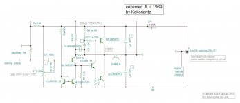
technical details
The main reason of this circuit as mentioned earlier, is to function with a constant current power supply .
The driver orders the outputs carrying the current A , increase in one and decrease in the other by i amps . The PS seeing the one output asking less current sparks the i current in excess thru its opposite capacitor by inertia (induction) trying to join its other pole. Meanwhile the second output which was receiving the current A from the first now gets i amps less , which in turn due to its inertia will pump it from its opposite capacitor via the load . The PS i current now cannot join the other pole by the second capacitor carrying an opposite transient current ,but must flow via the load and the second output , which has received order to acquire the extra i amps . By this the load sees both transient currents pass thru it and this on both phases . This yields a superior dynamic sound than single ended tube amps where only one phase , upon the collapse of the electromagnet, that such phenomena occurs.
The PS now sees the amplifier demanding a continuous current A ,but there is also the bootstrap capacitor . When the upper output voltage increases, the capacitor discharges thru the upper transistor as an autonomous circuit , but when the output decreases, the capacitor is charged by the lower transistor from the PS. this provokes a dissymmetric ac current ,but only 1/16 of the output current . A switching PSU can be used successfully providing 27v 1.25A . A 50watt shall be sufficient.
The load now is referenced to a floating point , whereas the input is referenced to 0v . It is natural that the floating center point becomes now the reference common ground and the whole circuit instead is floating. This why each channel needs its own PS. The reactance of the output capacitors do not take part any more of the feedback . It also allows the coupling capacitor to fly away. Now the input transistor gets its current from the devider emitter resistor via the load ,in order to keep it supplied unloaded , a pull up resistor is necessary . How much is the current that the input transistor needs ? A miserable 200u amp. The transistor is working in starvation regime! By humanity ,I decided to redesign this amp properly .
The designer was obliged to run it in starved mode ,as pulling more current by decreasing the collector resistor would decrease the open loop gain . So I added a CCS made by a paire of bc337 (2n2222 could have been used in Oxford) in current mirror, but of how much current? Auditively , up to 3ma there is enhancement, so let it be 3.5ma by 8.2k pull up resistor . This doubled the input's gain . Now I can reduce the collector resistor , Additively down to 4.7k gives considerable quality gain but later on simulator, it showed 3.3k gives the lowest distortion ,so let it be 3.3k . The transistor now has 4ma bias current and 3.9k pull up resistor can bring to 13.5v the output capacitors without load.
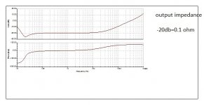
The base of the lower output transistor with its 15 ohm impedance sees the emitter of the driver now as 22ohm . The 2n3055 has particular linearity in Vbe/Ic transfer function and it pleases to be driven in voltage rather than current ,but what is this 2.2k resistor's function ? Normally it pulls extra current from the driver so that when the lower transistor reaches to cutoff ,it remains comfortably biased and it's not the case here. Additively again I decreased the value to 1k for better sound ,below is the same . On simulator it showed slight decrease in phase shift above 5 khz . The 2n3055 is of old type transistors that has along Ft a Fhfe of >10khz according Siemens datasheet. Motorola ones are may be 20khz. Normally a 3 stage amplifier requires a miller capacitor acting as dominant pole to achieve stability . With 2n3055 the dominant pole is inherent all naturally .The impedance curve which reflects the invers function of the open loop response shows clearly the 20khz dominant pole. It is possible that the 1k resistor is increasing the frequencies of other poles linked to the transistor as it shunts the b-e and c-b capacitors ,and leaves the dominant pole act alone, while the emitter follower at transients goes high impedance due to its b-e capacitor . In other words, if 2.2k was adequate for MJ480 ,1k is for 2n3055.
The circuit, Chinese JLH1969, has placed 220 ohm 1/4w(dissipating 1/2w) pull up resistor and adjustable resistor to be 68 ohms for 1.2A ,along bootstrap capacitor of 220uf. Across 220 ohm measured 10v,. that is a dc current of 45.5 ma to make the two outputs conduct 1.2A each . This gives an average beta of 50 . The 68 ohms shunts the b-e along with the bootstrap reducing its dynamic hfe by 20% . To higher the shunting resistor I swapped the resistors , 1w 220 ohm shunt and 2w 68 for pull up , the bootstrap capacitor to be 1500uf. Now the sound became sublime . Using the simulator it showed that the best value for the shunt is 250 ohm , this means the pull up should be unacceptable 39 ohms .
The transistor with the highest beta than , should be placed on the upper side ,to compensate the 220 ohm shunting of 7%. The 68 ohm receiving the same output ac voltage can dissipate 1.2w .
The JLH characteristics are measured by mj480 with beta of 140 . The open loop gain using 2n3055 of beta 50 requires increase in gain at the input stage ,as now it is possible . By how much ? To bring the output impedance to 0.16 ohm it needed to be doubled. The emitter resistor of the input stage 220 ohm is replaced by 100 ohm to double the open loop gain and the feedback resistor becomes 1.2k . Now the amplifier complies with the JLH specifications .
This amplifier as the original, requires also a roll-off capacitor of 220pf shunting the 1.2k feedback resistor, after which the frequency response becomes Bessel 570khz instead of Butterworth 100khz for the original . JLH advises not to use any , I leave it up to you to decide eider perfect square wave response or high slew rate .
The input bias voltage I transformed it into current bias by 470k . This way it does not require a supply filtering , the input capacitor with 470k does filter , but not on sub frequencies where it introduces a feedback from the floating supply . This gives a second order high cut function with its resonance and Q . The input R3C1 adjust these parameters . Similar function results in amplifiers using servo for automatic offset adjust. The input capacitor C1 must be more than 10uf to ensure low distortion at low frequencies . An input volume of 2k is possible .
This amp wakes up and sleeps politely .
See also " modification underway " post.
Kokoriantz
The main reason of this circuit as mentioned earlier, is to function with a constant current power supply .
The driver orders the outputs carrying the current A , increase in one and decrease in the other by i amps . The PS seeing the one output asking less current sparks the i current in excess thru its opposite capacitor by inertia (induction) trying to join its other pole. Meanwhile the second output which was receiving the current A from the first now gets i amps less , which in turn due to its inertia will pump it from its opposite capacitor via the load . The PS i current now cannot join the other pole by the second capacitor carrying an opposite transient current ,but must flow via the load and the second output , which has received order to acquire the extra i amps . By this the load sees both transient currents pass thru it and this on both phases . This yields a superior dynamic sound than single ended tube amps where only one phase , upon the collapse of the electromagnet, that such phenomena occurs.
The PS now sees the amplifier demanding a continuous current A ,but there is also the bootstrap capacitor . When the upper output voltage increases, the capacitor discharges thru the upper transistor as an autonomous circuit , but when the output decreases, the capacitor is charged by the lower transistor from the PS. this provokes a dissymmetric ac current ,but only 1/16 of the output current . A switching PSU can be used successfully providing 27v 1.25A . A 50watt shall be sufficient.
The load now is referenced to a floating point , whereas the input is referenced to 0v . It is natural that the floating center point becomes now the reference common ground and the whole circuit instead is floating. This why each channel needs its own PS. The reactance of the output capacitors do not take part any more of the feedback . It also allows the coupling capacitor to fly away. Now the input transistor gets its current from the devider emitter resistor via the load ,in order to keep it supplied unloaded , a pull up resistor is necessary . How much is the current that the input transistor needs ? A miserable 200u amp. The transistor is working in starvation regime! By humanity ,I decided to redesign this amp properly .
The designer was obliged to run it in starved mode ,as pulling more current by decreasing the collector resistor would decrease the open loop gain . So I added a CCS made by a paire of bc337 (2n2222 could have been used in Oxford) in current mirror, but of how much current? Auditively , up to 3ma there is enhancement, so let it be 3.5ma by 8.2k pull up resistor . This doubled the input's gain . Now I can reduce the collector resistor , Additively down to 4.7k gives considerable quality gain but later on simulator, it showed 3.3k gives the lowest distortion ,so let it be 3.3k . The transistor now has 4ma bias current and 3.9k pull up resistor can bring to 13.5v the output capacitors without load.
The base of the lower output transistor with its 15 ohm impedance sees the emitter of the driver now as 22ohm . The 2n3055 has particular linearity in Vbe/Ic transfer function and it pleases to be driven in voltage rather than current ,but what is this 2.2k resistor's function ? Normally it pulls extra current from the driver so that when the lower transistor reaches to cutoff ,it remains comfortably biased and it's not the case here. Additively again I decreased the value to 1k for better sound ,below is the same . On simulator it showed slight decrease in phase shift above 5 khz . The 2n3055 is of old type transistors that has along Ft a Fhfe of >10khz according Siemens datasheet. Motorola ones are may be 20khz. Normally a 3 stage amplifier requires a miller capacitor acting as dominant pole to achieve stability . With 2n3055 the dominant pole is inherent all naturally .The impedance curve which reflects the invers function of the open loop response shows clearly the 20khz dominant pole. It is possible that the 1k resistor is increasing the frequencies of other poles linked to the transistor as it shunts the b-e and c-b capacitors ,and leaves the dominant pole act alone, while the emitter follower at transients goes high impedance due to its b-e capacitor . In other words, if 2.2k was adequate for MJ480 ,1k is for 2n3055.
The circuit, Chinese JLH1969, has placed 220 ohm 1/4w(dissipating 1/2w) pull up resistor and adjustable resistor to be 68 ohms for 1.2A ,along bootstrap capacitor of 220uf. Across 220 ohm measured 10v,. that is a dc current of 45.5 ma to make the two outputs conduct 1.2A each . This gives an average beta of 50 . The 68 ohms shunts the b-e along with the bootstrap reducing its dynamic hfe by 20% . To higher the shunting resistor I swapped the resistors , 1w 220 ohm shunt and 2w 68 for pull up , the bootstrap capacitor to be 1500uf. Now the sound became sublime . Using the simulator it showed that the best value for the shunt is 250 ohm , this means the pull up should be unacceptable 39 ohms .
The transistor with the highest beta than , should be placed on the upper side ,to compensate the 220 ohm shunting of 7%. The 68 ohm receiving the same output ac voltage can dissipate 1.2w .
The JLH characteristics are measured by mj480 with beta of 140 . The open loop gain using 2n3055 of beta 50 requires increase in gain at the input stage ,as now it is possible . By how much ? To bring the output impedance to 0.16 ohm it needed to be doubled. The emitter resistor of the input stage 220 ohm is replaced by 100 ohm to double the open loop gain and the feedback resistor becomes 1.2k . Now the amplifier complies with the JLH specifications .
This amplifier as the original, requires also a roll-off capacitor of 220pf shunting the 1.2k feedback resistor, after which the frequency response becomes Bessel 570khz instead of Butterworth 100khz for the original . JLH advises not to use any , I leave it up to you to decide eider perfect square wave response or high slew rate .
The input bias voltage I transformed it into current bias by 470k . This way it does not require a supply filtering , the input capacitor with 470k does filter , but not on sub frequencies where it introduces a feedback from the floating supply . This gives a second order high cut function with its resonance and Q . The input R3C1 adjust these parameters . Similar function results in amplifiers using servo for automatic offset adjust. The input capacitor C1 must be more than 10uf to ensure low distortion at low frequencies . An input volume of 2k is possible .
This amp wakes up and sleeps politely .
See also " modification underway " post.
Kokoriantz
Attachments

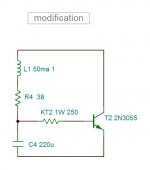
modification underway
The bootstrap circuit as seen has two problems to resolve .
The shunt resistor needs to be 250 ohm for best frequency responce of the upper output transistor.
The pull up resistor is loading the output too heavily pumping 12% from its power and polluting the PS .
The remedy I will try out in compliance with 1969 technology , is to supply the bias current by a choke . 1H/50ma can be sufficient , but its resistance should be less than 30 ohm . The choke must be small enough to be installed upon the heatsink adapter mounted by the same screws joining the heatsink .
I will go DIY mode and wind it myself . I'll report about it in few months .
Attachments
construction
To built this amp you need to buy in kit the Chinese JLH1969 .
https://www.aliexpress.com/item/2017new-1pcs-diy-kits-JLH-1969-class-A-amplifier-Board-high-quality-PCB-Assembled-MOT-2N3055/32800895221.html?spm=a2g0s.9042311.0.0.3da24c4d1y3S5A there is also on ebay .
The kit has genuine NOS transistors with best 2n3055 motorola, dark grey steal feet (hard to cut). Beside the transistors and accessories you need the 8.2k and 100k adj , (led + 10k) from the kit.
You need to buy / channel.
5 x bc337/(25 or 40)
100 ohm, 1k, 1.2k, 3.3k, 470k, 3.9k/0.5W, 220ohm/1W, 68ohm/2W
10uF/6.3v audio ( or 100uf from kit) , 1500uF/25v, 2x10000uF/25v Low ESR
small universal fiberglass board.
6 screw isolatorfor to-03 /220 , 7 ring terminals for 2.5mm screw , copper wire 1mm 40cm.
3 screw 2.5mmx20mm + nuts, 2xscrew 3mm and washers for heatsink.
Heatsink and 24v/2A minimum switching power supply .
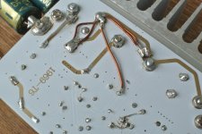
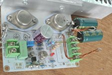
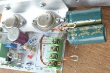
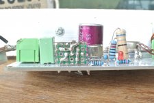
Before mounting the heatsink adapter upon the pcb , you must cover with an adhesive tape all the holes of the output transistors and the new two holes drilled and chamfered . One pair of isolators get their cylindrical parts cut to isolate the edge screws from the pcb . The other four need the circles trimed to be whole cylinders to insert in the heatsink holes of collector screws .
The pcb needs to have 3 tracks cut . The bootstrap capacitor must not link the collector but the emitter of the other transistor in star point . The 100k adjust have the central and an edge link cut as well as the edge to R3 . The central links instead R3 and the edge the 0v (precedent ground) . All the component refrences on the board are correspondence with the schematic. R8 is replaced with a strap bearing 27v to feed the pull up resistor of the CCS. R2&R10 are free.
One of the 2n3055 bears a handwritten number (higher beta). It must be installed near the output capacitors.
The heatsink used is 8inches wide 1 1/2 inches high and about 4cm thick . Sited on table rises at ambient T 30C° to 66C.
You always get a matched pair from the same lot of 5 pieces . To match, measure without touching the transistors with a digital multimeter on diode position . The red probe shorts b+c , The voltage drop should be equal.
https://www.aliexpress.com/item/Seven-Neon-Free-shipping-high-quality-ultral-thin-AC100-240V-DC-24V-4A-96W-switching/32799434842.html?spm=a2g0s.9042311.0.0.27424c4d18YyEG
To built this amp you need to buy in kit the Chinese JLH1969 .
https://www.aliexpress.com/item/2017new-1pcs-diy-kits-JLH-1969-class-A-amplifier-Board-high-quality-PCB-Assembled-MOT-2N3055/32800895221.html?spm=a2g0s.9042311.0.0.3da24c4d1y3S5A there is also on ebay .
The kit has genuine NOS transistors with best 2n3055 motorola, dark grey steal feet (hard to cut). Beside the transistors and accessories you need the 8.2k and 100k adj , (led + 10k) from the kit.
You need to buy / channel.
5 x bc337/(25 or 40)
100 ohm, 1k, 1.2k, 3.3k, 470k, 3.9k/0.5W, 220ohm/1W, 68ohm/2W
10uF/6.3v audio ( or 100uf from kit) , 1500uF/25v, 2x10000uF/25v Low ESR
small universal fiberglass board.
6 screw isolatorfor to-03 /220 , 7 ring terminals for 2.5mm screw , copper wire 1mm 40cm.
3 screw 2.5mmx20mm + nuts, 2xscrew 3mm and washers for heatsink.
Heatsink and 24v/2A minimum switching power supply .
Before mounting the heatsink adapter upon the pcb , you must cover with an adhesive tape all the holes of the output transistors and the new two holes drilled and chamfered . One pair of isolators get their cylindrical parts cut to isolate the edge screws from the pcb . The other four need the circles trimed to be whole cylinders to insert in the heatsink holes of collector screws .
The pcb needs to have 3 tracks cut . The bootstrap capacitor must not link the collector but the emitter of the other transistor in star point . The 100k adjust have the central and an edge link cut as well as the edge to R3 . The central links instead R3 and the edge the 0v (precedent ground) . All the component refrences on the board are correspondence with the schematic. R8 is replaced with a strap bearing 27v to feed the pull up resistor of the CCS. R2&R10 are free.
One of the 2n3055 bears a handwritten number (higher beta). It must be installed near the output capacitors.
The heatsink used is 8inches wide 1 1/2 inches high and about 4cm thick . Sited on table rises at ambient T 30C° to 66C.
You always get a matched pair from the same lot of 5 pieces . To match, measure without touching the transistors with a digital multimeter on diode position . The red probe shorts b+c , The voltage drop should be equal.
https://www.aliexpress.com/item/Seven-Neon-Free-shipping-high-quality-ultral-thin-AC100-240V-DC-24V-4A-96W-switching/32799434842.html?spm=a2g0s.9042311.0.0.27424c4d18YyEG
Attachments
Funny thing is that you mention 1K being the optimal value for the 3055 b-e resistor. I empirically arrived at 1K2 (with TIP3055 or small MJE3055). I even mentioned that in the main jlh thread a couple days ago. I'm also seeing some other similarities in the bootstrap (not the choke).
Member
Joined 2009
Paid Member
A couple of thoughts. Why not try it without R1 ? by removing it you no longer shunt the current source load on the input device collector which may improve linearity.
Also, in my JLH (it's a separate thread called "TGM9") I used an RC rail filter between the output stage and the bootstrap current source - in simulations it makes a significant improvement in the PSRR of the amplifier.
Also, in my JLH (it's a separate thread called "TGM9") I used an RC rail filter between the output stage and the bootstrap current source - in simulations it makes a significant improvement in the PSRR of the amplifier.
huggygood: I assure you will not go to bed a single night like un orphant child who didn't got his SE 300b. Mine is blushing in shame .
anti : Thank you for you fidelity . If you have a look on post 5229 posted 2days before yours, you can read "..... no any courageous Oxfordien has tried out 1k as I did."
nigelwright7557: Once you hear the sound ,you run about hailing , my God, my country , my family , my 3055 , as I am doing these days.
begun: Yes in ordinary amplifier it will behave as you describe . Here the story is different in two aspects . Objectively speaking with numbers , the distortion on simulator 9w/50hz passes from 0.03% to 0.11% . Wait a minute , The open loop gain is more than doubled . To keep the same NBF for similar stability as the original , the input gain should be halved . The distortion becomes 0.22%. Result the distorion increases by 730%. These are just commercial numbers to convince a naïve , because subjectively speaking ,I , unlike most members ,I don't here odd ordre harmonics below 0.3% and 1.2% for evens . What I do hear clearly if the sound is dark gray , gray , or colorful , without R1 the sound is dark gray.
I explain , imagine the amplifier to be a tube that music will be squeezed out , as the Signal tooth past brand that red and white color strips comes out of it. Imagine each voice/instrument is a certain recognisable color, if few colors are squeezed out, there is no problem , if it is hundreds of colors has to pass thru , a bad amplifier mixes them and you get eider dark gray single instument sound , or blurred colors with deformed unrecognizable instrument sound. Whereas the colorful sound is the one that provokes in your ears pleasure. Just consider two trumpets one saxo and a trombone combination. In real world you get a very pleasant beat , but reproduced, the amplifier as an unfocused lens blurs ,and the beat transforms into distortion, instead of inducing pleasure you get discomfort or at best disconcern.
If you higer the resistor, the driver's reverse capacitor gets less damped and the driver functions more as an integrator. I tried on simulator to lower further the R1 to 2.7k and increase the input gain by reducing 100 /1.2k to 82/1k , the distortion got higher. So let it remain 3.3k.
"huggygood: I assure you will not go to bed a single night like un orphant child who didn't got his SE 300b. Mine is blushing in shame ."
that's exactly it, but before, I have to understand what I'm doing")
I started like that with transistors, with super complicated stuff with lots of pieces, to finish over twenty years later with pcb big as packets of cigarettes and no more than 25 components per pcb,except for the naim, NVA and some schema that I like a lot.
that's exactly it, but before, I have to understand what I'm doing
I started like that with transistors, with super complicated stuff with lots of pieces, to finish over twenty years later with pcb big as packets of cigarettes and no more than 25 components per pcb,except for the naim, NVA and some schema that I like a lot.
First off, a big thank you for keeping a legend alive!!
I am in the 'senior league' and, naturally, over the years I had taken a lot of interest in the legendary design by JL-H. Of course, I refer to the improvements by JL-H himself and the later implementations by many talented hobbyists.
All said, the original design, IMHO, did retain a certain 'magic' that drew the serious listener to it, particularly when the aim was the reproduction of reality with a large degree of fidelity. I am one who is content to pursue that and choose not to be troubled by the lack of a "ruler-flat reproduction of everything from 20 to 20k". Surely the type of music one mostly listens to influences such attitudes, I must admit. I am no measurement pundit, though I have a lot of respect for such data. But I dare say I had disappointing experiences with many pieces of gear that measured very well. I am aware of the many factors that would have contributed to the negative impression. But when you spend serious (for you!) money and after a lot of experiments discover that you cannot live with a particular piece of kit, you tend to put the maximum distance between yourself and that equipment. But the JL-H amp had remained very close to my heart (and ears!) over the decades.
Your 'sublime' take on the classic JL-H amp has once again kindled my interest and it is going to be another favourite project -- ASAP!
Couple of queries.
Do you think there will be some difference in subjective performance if we make up Ca and Cb from a parallel bank of caps? (I have in mind the comment by the Grand Old Man of audio Jean HIraga that he preferred listening to a battery-powered amp, as he heard a difference between a really good PSU and a battery.) A PSU-agnostic amp is always desirable, and if the above will take it closer to a battery, all the better. At 24V, it will be easy to make comparisons, I believe. Also, will it make a difference if we take the same approach to the bootstrap cap.
Again, have you tried different active devices, and what are your recommendations? I have quite a few pairs of 2N3055 (TO-3) transistors (currently in production by Bharat Electronics in India), but I might have to substitute some of the other devices, and hence the query.
Thank you for helping us dream of reaching the moon for a few pennies!
For this particular amp, you better wait for the OP author to answer; but otherwise a tested combination is BC560C/BD139-16/2N3055 (or TIP3055).
For some reason, metal-can BJTs sound different. Hard to measure, but can be heard in-vivo. Also valid in guitar or studio circuits.
For some reason, metal-can BJTs sound different. Hard to measure, but can be heard in-vivo. Also valid in guitar or studio circuits.
The power rails are only tied to signal ground via capacitors. The rails are inputs to the signal path via R3. The signal on the power rails is related to the current through the speaker. So, as frequency drops, more of the speaker current signal is fed into the signal path.
Last edited:
wire thickness vs current in audio amplifiers
I seize the opportunity , to present discreetly , a controversial electrical subject which has paramount importance in audio transistor amplifiers , although forgotten by the most learned academics on this planet .
There is a table of wires called American Wire gauge Table (found easily on line) gives details about wire sizes . It shows that 1.026mm wire No18 has skin effect frequency of 17khz. This is the thickest wire that can be used in audio applications . If you look what current this wire should carry , one rows saying "maximum amps for power transmission"(used regorously for transformer winding calculations) of 2.3A and another row saying " maximum amps for chassis wiring 16A . What does this means? I invite you ,to have look on web to see the ignorance of lesson givers on this subject . Thomas Edison on his research for adequate wire for his electrical lamp , discovered this phenomena , that the resistivity of a wire varies in function of the current that flows through it . A copper wire of 0.1mm is known experimentally that it cannot pass more than 3amps. Whatever is it's length it gets destroyde . 30 years after inventing the lamp Edison making use of this phenomena , by using fused metal wire instead of copper , patented the Fuse.
If the magnetic field that the wire generates is constrained around the wire ,the resistivity remains constant at much higher currents ,this what high voltage power transmission engineering and capacitor manufacturers know well about . The chassis wiring means steal chassis. For high current capacitors as ceramic or electrolytic , to pass high currents through 0.7mm wire the manufecturers use iron allow copper wires (magnetic) to constrain the magnetic field . Early transistors with metal cans ,were also made with magnetic leads , particularly high current TO-03 ones for industrial/military versions had their emitter ,base leads made of high permeability alloy steal( Motorola). Nowadays all new casing transistors use only copper leads.
In audio amplifiers the current of music program is inversely proportional to the frequency . If the wires , PCB tracts do not have sufficient thickness the sound looses the energy in low frequency and sounds bright or I should say transistor. In tube world ,where currents are low , normal wire thickness do not interfere, which results better bass performance ,limited only by the OPT . On the other hand if it happens that the transistor amplifier is wired ,respecting wire thickness table, the result is spectacular.
The Prof: Allow me few minutes to convinced definitively that these four transistors although old types are still the best possible available components for this amplifier . First of all , my duty in this project is similar to that of an architect who restores an ancient monument . I need to respect scrupulously the spirit of the architect's initial design .
Any three stage amplifier when feedback , becomes an oscillator , as each stage can shift up to 90° than at a certain frequency the feedback shifts 180° and oscillates . To make the amplfier back a stable amplifier two of the stages must start shifting at very high frequencies and force the third stage to shift at much lower one so that it remains the only shifter in the whole range ,It is called the dominant pole . The open loop frequency responce of such amplifiers are between 100hz to 500hz ,rare are high end amps up to 2khz . In this amplfier the designer was obliged due to early stage of transistor technolgy to atribute the dominant pole to the output stage . The 2n3055 limits itself to 20khz . For this the two other stages should be the highest possible . The amplifier with such configuration passes up to 20khz signal to the output untouched . This is the spirit of JLH1969 . There is no any better low speed transistor ,as linear Vbe/Ic function available . Lets consider the two othe old coucous . The 2n2907a here functions as voltage error amplifier . It compares the input on its base with that of the feedback presented by 100 ohm ,and produces an error current .
The best transistor in our times for this task is bc327. Comparing them on simulator the two exhibit exactly the same distortion ,the same harmonic ratios ,the same frequency responce 100mhz, but the 2907 has a c-b capacitance of 8pf instead 15for the bc327 allows an eventual input volume of 2k insread of 1k . In other word the 2n2907a is still better than the best. The othe coucou the 2n1711 is a high speed transistor of 300mhz Ft 4pf c-b and a typical beta of 150 at working bias . Only video transistors can compete with it , but the video transistors developed are eider high voltage hence lower beta or higher power hence higher c-b capacitance . This makes the old coucou to be the best high speed driver ever . Now you can bless the name of the person of great knowledge, who not only chose these transistors but also could gather them for you first choice components. example ,the 2n2907a later production is of aluminum casing ,NO he chose the expensive nos ones. The 2n3055 you said it youself are now india made NO ,he chose the the best dark gray steal footed Motorola rare to find ones. Even this thunder tream of four transistors are sold alone at 3times of the kit's price is still a bargain . Go on line and try to find these by youself ,I couldn't.
You are proposing to power by batteries, All shows that the purpose of the existance of this ampilfier described on the first post was not clear for you . In short the amplifier is designed to draw a continuous current after which any power supply doesn't effect the sound. Slim switching PSU that can be installed very near the amp with short wires, wound be better than bulky long wires of batteries. The Ca,and Cb aren't reservoire capacitors but create a floating ground . As the feedback considers only the voltage across the output , it's value in uf is less importance than its ESR . Thats why these capacitors must be installed nearest possible with shortest leads . paralleling a second pair is possible by having one pair horizontal other vertically mounted ,but challenging at soldering. The effect on sound occurs on explosions , if the ESR is not low it thunders instead . For soldering/unsoldering difficulties and neighborhoud allowance reasons , I 'll review it with Nichicon FW capacitor . see
https://www.youtube.com/watch?v=dEDtJrhAkF0
https://www.youtube.com/watch?v=Ehm4HLnr-FQ
With Nichicon 10000uf/50v 8$ /pair and see if I get something better. I am sure one pair of these should be sufficient.
traderbam; I explained this fact in technical details . It is the voltage of the output capacitors forming high pass with the load find feedback with the high pass of the input . It results into second order high pass function as servo automatic offset adjust does. With input capacitor of 33nf it forms Butterworth 10hz , but the distortion at 50hz rises considerably . With 10uf the resonance is 2.5hz but with Q of3 ,10db. Max . 100uf can be used if the output capacitors are 25v , because at start up the output remains 0v for 4seconds and upper capacitor is in surge 10% . By voltage rating it is allowed only 10 seconds.
- Status
- This old topic is closed. If you want to reopen this topic, contact a moderator using the "Report Post" button.
- Home
- Amplifiers
- Solid State
- sublimed JLH1969