Hi all,
I have been watching and reading in this forum for quite a while and have now decided to post something of potential interest.
I have a pair of SB23NBACS45-8 drivers that I'm not using at present, so I thought about going out on a limb and doing a 2 way TL. Crazy, maybe, but I have just measured the drivers in DATS, and they are really suited to closed box or TL use. The Qts is 0.5, Fs is 31Hz, VAS is 49.32L, Qms is 8.1, Qes is 0.54.
I have modelled the data into Leonard Audio TL software and it looks good.
I have my own FR data on a 30 x 60 baffle and the cone breakups are really easily tamed. Attached is my preliminary data on a 30 x 90 baffle. Woofer at pretty much the top of the baffle and tweeter directly underneath the woofer. I'm using the SB29RDCN tweeter, so the centre to centre distance between drivers is only 155mm. Crossover point is 1370Hz. Will be driven with 20W max.
What does everyone think?
Attachments
Don't know where you found that, but I just looked at SB's published specs for this woofer and it showed a Qts of 0.40 and an fS of 25 Hz. Those two values suggest the optimum TL tuning frequency would be equal or close to 25 Hz. The OP measured an fS of 31 Hz and a Qts of 0.5, but those two values also indicate a tuning frequency around 25 Hz would be optimum because the two ratios of fS/Qts are all but identical, 62.5 from SB's specs and 62 from the OP's measurements.
Paul
SB23NBACS45-8 8" Black Aluminum Cone
Paul
SB23NBACS45-8 8" Black Aluminum Cone
I tried to find data on that woofer and the stated Qts is 0.33.Which would not suit a sealed box.
I really like the SB29RDCN, but I'd be concerned about crossing it that low. It looks like it's about 1100 - 1250 Hz. You're using a 2nd order electrical, so I'd worry about distortion going that low. I have seen the full size ferrite version (SB29RDC) taken as low as 1100 Hz, but it used a 4th order electrical for a LR6 acoustical roll off. Here's the LINK. Look for the "Low Crossover LR6" design.
Last edited:
Tapered TL model
I modeled a 10:1 tapered TL for this woofer using SB's published specs. The line length is 70" and has a net volume of ~3.3 cubic feet (starting area of 10" x 15" and ending area of 10" x 1.5"). The woofer's center is located 14" from the beginning of the line, and the first 47" of the line is filled with polyester fiber at a density of 0.75 lb/ft3. The line's tuning frequency is 24-25 Hz. I modeled with 0.5 ohms added in series with the woofer to represent the resistance of a series crossover inductor. Below is the predicted anechoic system bass response (red line) for an input of 18w/1m into this nominal 6.5-ohm impedance. F3 in my model is ~28 Hz, but could be lowered simply by increasing the line's volume. Using the OP's measured T/S values I'd expect very similar results, but he didn't list several parameter values needed (Re, Le, Bl and Sd), so I couldn't verify my assumption. I also agree that the proposed crossover corner is very likely too low for the tweeter.
Paul
Attachments
I tried to find data on that woofer and the stated Qts is 0.33.Which would not suit a sealed box.
That's the dash 4 (4 ohm) variant. Eventually found the data on SB's site.
Thanks for the comments. I have been doing some tweaking over the weekend and have come up with an approx 1500Hz crossover point. I’ll take on the task of trying an LR4 slope on the tweeter. The other woofer data is as follows: Re is 5.53 ohms, Le is 0.7mH at 1kHz, BL is 8.681, and Sd is 216cm2.
My modelled TL is 2.2 m long, 5:1 ratio with Sd1 of 500cm2 and Sd2 of 100cm2, driver at 76cm. Heavy fill of 2.5kg/m3 in the first 1.4m of the line.
My modelled TL is 2.2 m long, 5:1 ratio with Sd1 of 500cm2 and Sd2 of 100cm2, driver at 76cm. Heavy fill of 2.5kg/m3 in the first 1.4m of the line.
I substituted your T/S measurements into my model without any other changes, resulting in the predicted anechoic system bass response (red line) attached below. The only real change is a slightly lower output SPL (0.6 dB lower) but the same f3 for the same input power I used. A shorter line with a larger taper ratio does wonders for smoothing out the ripples in the response above 200 Hz or so and allows a lighter stuffing density. Your stuffing density works out to be a bit less than 1.6 lb/ft3 and unnecessarily makes f3 higher (a stuffing density over 1 lb/ft3 usually means the basic TL design can be improved).
Paul
Paul
Thanks for the comments. I have been doing some tweaking over the weekend and have come up with an approx 1500Hz crossover point. I’ll take on the task of trying an LR4 slope on the tweeter. The other woofer data is as follows: Re is 5.53 ohms, Le is 0.7mH at 1kHz, BL is 8.681, and Sd is 216cm2.
My modelled TL is 2.2 m long, 5:1 ratio with Sd1 of 500cm2 and Sd2 of 100cm2, driver at 76cm. Heavy fill of 2.5kg/m3 in the first 1.4m of the line.
Attachments
Ok All,
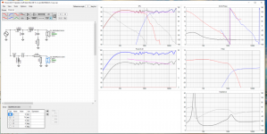
I have had a look at Zaphs pages on the crossover designs with SB29RDCN and have come up with a couple of solutions that I would like everyone to have a look at. First one is 1400Hz crossover 18db/octave and second one is 1250Hz crossover 24db/octave. 2nd pic is my current running version. Tweeter with reversed polarity. Very large suckout at crossover point when tweeter is normal polarity.
I'll put the above parameters into TL software and see if I can get a better response.
Cheers.
Attachments
I substituted your T/S measurements into my model without any other changes, resulting in the predicted anechoic system bass response (red line) attached below. The only real change is a slightly lower output SPL (0.6 dB lower) but the same f3 for the same input power I used. A shorter line with a larger taper ratio does wonders for smoothing out the ripples in the response above 200 Hz or so and allows a lighter stuffing density. Your stuffing density works out to be a bit less than 1.6 lb/ft3 and unnecessarily makes f3 higher (a stuffing density over 1 lb/ft3 usually means the basic TL design can be improved).
Paul
Thanks for the info Paul. I'll have another go at the TL software tonight using a larger taper ratio.
OK, now I'm struggling with the imperial to metric conversions of pounds/ft3 to kg/m3.
A fill rate of 0.75 pounds / ft3 = 340g/27L. To get to kg/m3 is a factor of 37, which would mean 12kg/m3.
1lb/ft3 = 16kg/m3. That's a lot of fill.
So in reality, my TL design with 2.5kg/m3 is the equivalent of 0.15lb/ft3, which I just checked with an online calculator.
Cheers.
A fill rate of 0.75 pounds / ft3 = 340g/27L. To get to kg/m3 is a factor of 37, which would mean 12kg/m3.
1lb/ft3 = 16kg/m3. That's a lot of fill.
So in reality, my TL design with 2.5kg/m3 is the equivalent of 0.15lb/ft3, which I just checked with an online calculator.
Cheers.
OK, now I'm struggling with the imperial to metric conversions of pounds/ft3 to kg/m3.
A fill rate of 0.75 pounds / ft3 = 340g/27L. To get to kg/m3 is a factor of 37, which would mean 12kg/m3.
1lb/ft3 = 16kg/m3. That's a lot of fill.
So in reality, my TL design with 2.5kg/m3 is the equivalent of 0.15lb/ft3, which I just checked with an online calculator.
Cheers.
Try thinking like a Neanderthal to deal with those non-metric measurements.Tony Abbott might be able to help you with that.

Yep, you are correct; I made a decimal point location error in converting cubic meters to cubic feet. That said, a stuffing density of 0.15 lb/ft3 is hardly a "heavy stuffing density" as you first described it and is woefully inadequate, explaining why your modeled responses with the LA software have such big dips in them above 200 Hz or so. Using a larger taper ratio will have very positive effects on smoothing the response, but even at 10:1, you'll end up with a very "bumpy" response unless you also use a stuffing density significantly larger than 2.5 kg/m3. Sorry about my mathematical mistake.
Paul
Paul
OK, now I'm struggling with the imperial to metric conversions of pounds/ft3 to kg/m3.
A fill rate of 0.75 pounds / ft3 = 340g/27L. To get to kg/m3 is a factor of 37, which would mean 12kg/m3.
1lb/ft3 = 16kg/m3. That's a lot of fill.
So in reality, my TL design with 2.5kg/m3 is the equivalent of 0.15lb/ft3, which I just checked with an online calculator.
Cheers.
Help this poor "Neanderthal" out a bit because I'm not entirely familiar with the LA software. Is the line length 140 or 190 cm and if 190, does the 140 cm indicate how far down the line the stuffing is located? The woofer's center is located 30 cm from the beginning of the line? Based on the listed starting and ending areas shown, it looks like the line has a nominal taper ratio of 2.5:1? I ask because I want to model your line with Martin King's software that I know is completely correct. One of the major problems with the LA software was its algorithm for stuffing density, and AFAIK it was never completely corrected. With such a low taper ratio and low stuffing density, assuming only the first 2/3 or less of the line is stuffed, the smoothness of your modeled response is questionable. I'm not criticizing your work, please understand, only hoping you don't end up with something rather different from and inferior to what you think you were going to achieve.
Thanks,
Paul
Thanks,
Paul
Here is the updated TL.
Fill is equivalent to 0.3lb / ft3.
Last edited:
Help this poor "Neanderthal" out a bit because I'm not entirely familiar with the LA software. Is the line length 140 or 190 cm and if 190, does the 140 cm indicate how far down the line the stuffing is located? The woofer's center is located 30 cm from the beginning of the line? Based on the listed starting and ending areas shown, it looks like the line has a nominal taper ratio of 2.5:1? I ask because I want to model your line with Martin King's software that I know is completely correct. One of the major problems with the LA software was its algorithm for stuffing density, and AFAIK it was never completely corrected. With such a low taper ratio and low stuffing density, assuming only the first 2/3 or less of the line is stuffed, the smoothness of your modeled response is questionable. I'm not criticizing your work, please understand, only hoping you don't end up with something rather different from and inferior to what you think you were going to achieve.
Thanks,
Paul
Thanks Paul.
The line overall length is 1.9m. Sd1=800cm2 and Sd2=100cm2. The driver is located 30cm from the closed end. The filling is in the first 1.4m of the line at a density of 5kg/m3. Now that I know this level of fill is considered “light”, I’ll have another go with a density of 8kg/m3 to see the effect.
Cheers
Jason
Last edited:
At first glance it appears both versions do a lot more to protect the tweeter down low. It would be informative to see how close these match to actual LR4/6/8 curves. Does VirtuixCAD have that capability? I'm used to Passive Crossover Designer (PCD) where you can pick a crossover type & slope as a target and design the crossover so the driver response matches that target.
Other than that it's down to measurements (on-axis, distortion, off axis, etc.) and listening to the drivers.
Other than that it's down to measurements (on-axis, distortion, off axis, etc.) and listening to the drivers.
Ok All,
I have had a look at Zaphs pages on the crossover designs with SB29RDCN and have come up with a couple of solutions that I would like everyone to have a look at. First one is 1400Hz crossover 18db/octave and second one is 1250Hz crossover 24db/octave. 2nd pic is my current running version. Tweeter with reversed polarity. Very large suckout at crossover point when tweeter is normal polarity.
I'll put the above parameters into TL software and see if I can get a better response.
Cheers.
The Re=6.5ohm Wavecor TW030WA12 is a 30mm dome tweeter in a modest depth waveguide which both extends the low frequency range and provides controlled directivity. Looks like another option for your 2-way design.
TW030WA11 and TW030WA12 are tweeters designed for the most demanding applications, where low resonance frequency, high sensitivity and power handling, controlled dispersion, and a very wide frequency range are required.
FEATURES
• Featuring waveguide face plate for controlled dispersion, offering optimized off-axis and power response
• 30 mm voice coil design with high power handling, and low resonance frequency
• Copper clad center pole yielding very low voice coil inductance for reduced distortion and increased high frequency output
• Internal volumes for low resonance frequency and distortion
• Precision-coated textile diaphragm for improved consistency and high-frequency extension
• Optimized dome shape for ultra high frequency cutoff
• Vented voice coil former for reduced distortion and compression
• Copper-clad aluminium voice coil wire offering lower moving mass for improved efficiency and transient response
• Build-in cavities under dome/edge to equalize pressure for lower distortion and lower resonance frequency
• Flexible lead wires for higher power handling and larger excursion
• Gold plated terminals to prevent oxidation and ensure long-term reliable connection
• Delivered with foam gasket attached for hassle-free mounting and secure cabinet sealing
- Status
- This old topic is closed. If you want to reopen this topic, contact a moderator using the "Report Post" button.
- Home
- Loudspeakers
- Multi-Way
- 2 way TL using SB23NBACS45 and SB29RDCN