Hi
I'm building a KT88 SE amp and would like to use a 12AT7 SRPP as a driver for the KT88 and a 2nd SRPP to drive a spring reverb tank. The 12AT7 max heater to cathode voltage is quite limiting when B+ is over 330v. If I raise the heater a lot for the top tube it starts getting too high for the bottom tube.
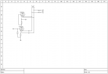
Is there anything wrong with using the triodes of one 12AT7 as the top triodes for both SRPPs with another 12AT7 providing the bottom SRPP triodes? Would this mean I could raise my heater supply as normal and then block the DC to the lower 12AT7 as in the attached schematic?
Cheers
Ben
I'm building a KT88 SE amp and would like to use a 12AT7 SRPP as a driver for the KT88 and a 2nd SRPP to drive a spring reverb tank. The 12AT7 max heater to cathode voltage is quite limiting when B+ is over 330v. If I raise the heater a lot for the top tube it starts getting too high for the bottom tube.
Is there anything wrong with using the triodes of one 12AT7 as the top triodes for both SRPPs with another 12AT7 providing the bottom SRPP triodes? Would this mean I could raise my heater supply as normal and then block the DC to the lower 12AT7 as in the attached schematic?
Cheers
Ben
Attachments

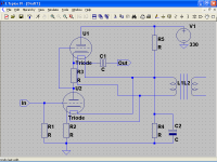
You could do it without problems. Look here :
http://forum.elektor.com/download/file.php?id=2705771&mode=view
http://forum.elektor.com/download/file.php?id=2705770&mode=view
About capacitor value : cutoff frequence are Fc = 1 / 2.PI.R.C
R are the Rg of the next stage.
http://forum.elektor.com/download/file.php?id=2705771&mode=view
http://forum.elektor.com/download/file.php?id=2705770&mode=view
About capacitor value : cutoff frequence are Fc = 1 / 2.PI.R.C
R are the Rg of the next stage.
Hi
I'm building a KT88 SE amp and would like to use a 12AT7 SRPP as a driver for the KT88 and a 2nd SRPP to drive a spring reverb tank. The 12AT7 max heater to cathode voltage is quite limiting when B+ is over 330v. If I raise the heater a lot for the top tube it starts getting too high for the bottom tube.
Is there anything wrong with using the triodes of one 12AT7 as the top triodes for both SRPPs with another 12AT7 providing the bottom SRPP triodes? Would this mean I could raise my heater supply as normal and then block the DC to the lower 12AT7 as in the attached schematic?
Cheers
Ben
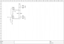
i) For the 12AT7 Vkf(max)=90V
ii) Your implementation to power heaters is wrong, if you use a double triode for the top and another for the bottom, you must use two heater supplies, both referenced to a given voltage.
If implemented correctly there is no need for such complication, just reference heaters to the correct value, i.e. +B/4=82.5V and both 12AT7 will be on specs.
C2 could be about 100µF/160V, select R4 and R5 for a current flow of about 1mA.
The attachment only shows one 12AT7 (I am to lazy, sorry) just connect al heaters in parallel.
Attachments
Last edited:
Have updated the schematic so now it has a ground reference on the non-raised heater supply.
Poplin - Why would this not work? I understand your point, I already built it very similarly to your schematic. The problem is I want to use a higher B+ than 330v!
Gug42 - Encouraging to see your prior project.
Cheers
Ben
Poplin - Why would this not work? I understand your point, I already built it very similarly to your schematic. The problem is I want to use a higher B+ than 330v!
Gug42 - Encouraging to see your prior project.
Cheers
Ben
Attachments
Not a good idea IMHO. Better to use both halves of the same tube as upper and lower triodes, instead of splitting as you do it. It works fine without elevation of the upper heating. Just tie one end to ground. Also better for symmetry, tube rolling and in case of tube aging or failure.
i) For the 12AT7 Vkf(max)=90V
ii) Your implementation to power heaters is wrong, if you use a double triode for the top and another for the bottom, you must use two heater supplies, both referenced to a given voltage.
If implemented correctly there is no need for such complication, just reference heaters to the correct value, i.e. +B/4=82.5V and both 12AT7 will be on specs.
C2 could be about 100µF/160V, select R4 and R5 for a current flow of about 1mA.
The attachment only shows one 12AT7 (I am to lazy, sorry) just connect al heaters in parallel.
Hi Popilin,
If I series the filaments and power them with 12V would this still apply?
Regards,
Silviu
The capacitive reactance of 39uF at 60Hz is 68 Ohms. Two 39uF caps gives you 136 Ohms in series with your 6.3VAC or 12.6VAC filament transformer. This will not work, there is no appreciable current through the filament. You would need 2 capacitors with many many times the capacitance, they will be expensive, and take up lots of real estate, at least you had the pair of resistors from the filament ends to ground. The capacitors must have a voltage rating of at least 170VDC. A 12AT7 filament is 0.15Amp @ 12.6V. 12.6V/0.15A = is 84 Ohms when hot. We are talking about two capacitors of at least 1000uF @ 200V each (Xc = 2.7 Ohms each) to get this method to work. It is better to use 6.3V filament, because the ends of the filaments are 3.15VAC versus ground, less hum interference versus 12VAC (filament ends 6.3VAC versus ground). But wiring the filaments for 6.3VAC requires two 2000uF capacitors. Do not 'fix' the problem this way.
Why not just add a small center tapped 6.3VAC (preferred), or center tapped 12.6VAC transformer, and raise the center tap to 170VDC?
By the way, putting a filament at 82.5VDC, with the cathode at 170VDC, is 87.5V difference. 90VDC spec - 87.5VDC = 2.5V. You only have 2.5Vpeak maximum signal before the voltage difference exceeds the 90V maximum spec. (not good).
Now you see one of the major reasons I do not like SRPP circuits. I prefer to use a triode on the bottom, and an IXYS current source on the top. It gets the same gain (or a little more gain than SRPP), and there is no extra raised filament requirement to worry about. If you do not like IXIS current sources, then use a discreet current source with BJTs or MOSFETs instead.
Happy re-designing. Happy listening.
Last edited:
6A3sUMMER - Thankyou for that explanation. I don't mind too much if it doesn't work as long as I know why!
I thought the capacitors would act, with the ground resistors, as a CR filter. I calculated the cutoff as I think 20hz with a 39uf cap and 200 ohm resistor . This isn't the case though?
I'm not in a position for a complete redesign. This will be the second incarnation of this amp, the case is made with the transformers and tubes mounted. For this reason I will stick to the SRPP plan this time, maybe next time I look at current sources.
I actually have another filament winding on my transformer. It is 12.6v though so I preferred not to use it if this plan would have worked. Maybe it is my best compromise at the moment though. I could raise the 12.6v and use it for the top triodes of the SRPPs, use the unraised 6.3v for the bottom triodes and preamp stage.
Why not just add a small center tapped 6.3VAC (preferred), or center tapped 12.6VAC transformer,
and raise the center tap to 170VDC?
Because if you must elevate heaters, it is better to do at about 30VDC with respect to cathode, then the center tap should raise at about 200VDC for the top triode and about 30VDC for the bottom triode, provided that you use two separated 12AT7.
By the way, putting a filament at 82.5VDC, with the cathode at 170VDC, is 87.5V difference. 90VDC spec - 87.5VDC = 2.5V. You only have 2.5Vpeak maximum signal before the voltage difference exceeds the 90V maximum spec. (not good).
Yes, you are right, I was thinking about low level applications.
Reading more carefully, the OP seem to build a guitar amp.
Last edited:
Since you can not add parts, or modify to use current sources, the best you can do is to use the 12.6VAC in an elevated mode for the top triode sections.
You designed an RC filter using 39uF and 200 Ohm resistors, but you forgot to include the 84 Ohms of the (hot) filament (@ 12.6V). The 84 Ohms is in parallel with the 200+200 Ohms (400 Ohms). That is 400 Ohms in parallel with 84 Ohms = 69.4 Ohms
And even if you re-calculate using 69.4 Ohms for -3dB bandwidth at 60Hz, that would give 0.707 x 12.6VAC = only 8.9VAC across the 12.6V filament. That is why you would need at least 1000uF @ 200V per capacitor to use that method (physically big caps in a limited real estate application).
Last edited:
By the way, putting a filament at 82.5VDC, with the cathode at 170VDC, is 87.5V difference. 90VDC spec - 87.5VDC = 2.5V. You only have 2.5Vpeak maximum signal before the voltage difference exceeds the 90V maximum spec. (not good).
Yes, you are right, I was thinking about low level applications.
Ah, by the way, see here
http://www.diyaudio.com/forums/tubes-valves/49567-unison-research-smart-845-schematics-3.html#post687152
This renowned commercial product used a +B of about 660VDC for the ECC82, and its heaters are elevated at about 160VDC, top triode cathode is at about 350VDC, clearly Vkf~190V is out of specs by about 10V, not to speak that an 845 needs a lot drive voltage, anyway I did not see complains against squealing...
Last edited:
Reading more carefully, the OP seem to build a guitar amp.
Almost! Building an amp for my violin, piezo pickup. No one makes a commercial product I'm happy with so build I must.
- Status
- This old topic is closed. If you want to reopen this topic, contact a moderator using the "Report Post" button.
- Home
- Live Sound
- Instruments and Amps
- Splitting SRPP over 2 tubes and raising heater