Hello,
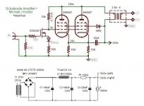
I am attempting to adapt Michael J. Koster’s Schadeode 6L6GC/5881 amp to work with 6W6GT in PSE. I am a paint-by-number builder so have limited knowledge, but am trying to learn. I would be very grateful for any criticisms and suggestions for the circuit I have come up with.
The output transformer I have is a Transcendar 10 watt 5k:8. My speakers are 4 ohm so the schematic shows it as a 2.5k:4. I hope this is OK. Would it be OK to use IXYS10M45 instead of the IXYS01N100?
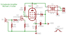
Here is the link to Mr. Koster's amp that I am trying to emulate. I've attached the schematic for that as well.
Tube DIY Asylum
Thank you all for your help.
I am attempting to adapt Michael J. Koster’s Schadeode 6L6GC/5881 amp to work with 6W6GT in PSE. I am a paint-by-number builder so have limited knowledge, but am trying to learn. I would be very grateful for any criticisms and suggestions for the circuit I have come up with.
The output transformer I have is a Transcendar 10 watt 5k:8. My speakers are 4 ohm so the schematic shows it as a 2.5k:4. I hope this is OK. Would it be OK to use IXYS10M45 instead of the IXYS01N100?
Here is the link to Mr. Koster's amp that I am trying to emulate. I've attached the schematic for that as well.
Tube DIY Asylum
Thank you all for your help.
Attachments
Well…
First and foremost, your MOSFET. ⁰¹n₁₀₀ is an enhancement mode device, meaning that it is OFF at 0 V gate bias. Having the 47 kΩ input impedance resistor hooked from gate to ground is a zero bias nominal position. Worse, with whatever current that flows thru MOSFET, the source-resistor (akin to a cathode resistor in a tube circuit) ends up negative relative biasing the gate. Even more into device's OFF condition.
“Apart from that Mrs. Lincoln, how did you enjoy the show?” … mmm is apt.
There are other oddities: why the powering of the 6W6 pair's grid–2 thru a Shotkey diode? Or doing so without a reservoir capacitor in parallel to ground? Or the function of the 1Nxxx diode on the source of the input MOSFET? Or the criticality of the input MOSFET's transconductance on actually establishing a 9 volt operating point for its drain?
I'll stop there. The consequences just seem to cascade from there.
GoatGuy
HOWEVER… since you're asking for HELP, try using a depletion mode MOSFET as the input. Depletion mode MOSFETS work much more akin to JFETs, which in turn work more like triodes, which in turn like "cathode self-bias" (source resistors).
Here's a good device: https://www.mouser.com/datasheet/2/268/supertex_lnd150-1181133.pdf
LND150D is the device. Has very JFET charateristics. Easy to use.
_______
However, establishing the right operating point seems dicey. I've got to leave now, so I can't offer a concrete circuit diagram alternative. Good luck!
GoatGuy
I think the MOSFET is supposed to be an 01N100D, which is the depletion mode version of that MOSFET.
https://www.mouser.com/ds/2/205/98809-1109866.pdf
https://www.mouser.com/ds/2/205/98809-1109866.pdf
You have to keep in mind that Michael Koster was one of those brilliant idea-generator type of guys and didn't always spell things out well for beginners and frequently took shortcuts in his drawings that would cause confusion.
The symbol is clearly for an enhancement device but I am confident that Koster used the 01N100D depletion device.
The symbol is clearly for an enhancement device but I am confident that Koster used the 01N100D depletion device.
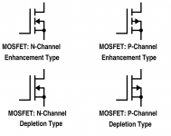
Yes, I think the symbol in the schematic is for the enhancement mode version, but the depletion mode version is what is actually used in the real world.
I hadn't given much thought to MOSFET symbols and what they mean, so I did a quick search and found this image. Is it accurate?
--
I hadn't given much thought to MOSFET symbols and what they mean, so I did a quick search and found this image. Is it accurate?
--
Attachments
Last edited:

Your amplifier:
1. You asked about using a 5k:8 Ohm transformer in place of a 4k:4 Ohm transformer.
Lets suppose the 5k:8 Ohm transformer has 250 Ohm primary DCR, and 0.4 Ohm secondary DCR.
The transformer loss due to DC resistance will be 1dB.
Now, use the same 5k:8 Ohm transformer in a 4k:4 Ohm circuit, the loss due to DC resistance will be 2dB.
Conclusion: Whatever loss there is due to DC resistance in the 5k:8 Ohm setup, it will be twice as much in the 4k:4 Ohm setup if you use a 5k:4 Ohm transformer.
2. The parallel 6W6GTs bypass cap of 20uF and effective 375 Ohm cathode resistor has a -3dB response at 21.2 Hz. Actually -3dB occurs at a higher frequency than that, because the 375 Ohms is in parallel with the two cathode’s parallel impedance. Plus there is the additional low frequency rolloff due to the output transformer’s low frequency rolloff.
Fix that:
It would be better to use a pair of 47uF or 100uF caps, one cap to one 700 Ohm resistor, and the other cap to the other 700 Ohm resistor, with the other ends of the caps to the bottom of the output transformers primary. Then, disconnect the connection from one 6W6GT cathode to the other 6W6GT cathode.
And get the following benefit:
That way, you can measure the individual voltage across each 700 Ohm resistor, to see if one 6W6GT is hogging more than its share of the current, Then you can find better matched 6W6GT tubes (matched in the circuit voltages and currents you are using, instead of at a different voltage and current rating on some tube tester).
3. Your amp is in pentode mode, even though it has Shade negative feedback, I would advise that you never operate it without a proper load resistor, or a loudspeaker.
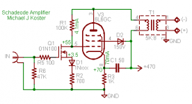
4. The original Koster amplifier has an output tube power dissipation problem:
The 5881 plate has 470V and the cathode has 70V. The plate current plus screen current is 70mA, most of that is the plate current. 470V - 70V = 400V plate to cathode.
470V x .07A = 28 Watts
The plate is rated for 23 Watts, and the screen is rated for 3 Watts. 23 + 3 = 26 Watts.
The tube is being used at 28 Watts, 2 watts beyond its maximum specification.
And most likely, most of that excess dissipation is likely going to the plate, not the screen.
1. You asked about using a 5k:8 Ohm transformer in place of a 4k:4 Ohm transformer.
Lets suppose the 5k:8 Ohm transformer has 250 Ohm primary DCR, and 0.4 Ohm secondary DCR.
The transformer loss due to DC resistance will be 1dB.
Now, use the same 5k:8 Ohm transformer in a 4k:4 Ohm circuit, the loss due to DC resistance will be 2dB.
Conclusion: Whatever loss there is due to DC resistance in the 5k:8 Ohm setup, it will be twice as much in the 4k:4 Ohm setup if you use a 5k:4 Ohm transformer.
2. The parallel 6W6GTs bypass cap of 20uF and effective 375 Ohm cathode resistor has a -3dB response at 21.2 Hz. Actually -3dB occurs at a higher frequency than that, because the 375 Ohms is in parallel with the two cathode’s parallel impedance. Plus there is the additional low frequency rolloff due to the output transformer’s low frequency rolloff.
Fix that:
It would be better to use a pair of 47uF or 100uF caps, one cap to one 700 Ohm resistor, and the other cap to the other 700 Ohm resistor, with the other ends of the caps to the bottom of the output transformers primary. Then, disconnect the connection from one 6W6GT cathode to the other 6W6GT cathode.
And get the following benefit:
That way, you can measure the individual voltage across each 700 Ohm resistor, to see if one 6W6GT is hogging more than its share of the current, Then you can find better matched 6W6GT tubes (matched in the circuit voltages and currents you are using, instead of at a different voltage and current rating on some tube tester).
3. Your amp is in pentode mode, even though it has Shade negative feedback, I would advise that you never operate it without a proper load resistor, or a loudspeaker.
4. The original Koster amplifier has an output tube power dissipation problem:
The 5881 plate has 470V and the cathode has 70V. The plate current plus screen current is 70mA, most of that is the plate current. 470V - 70V = 400V plate to cathode.
470V x .07A = 28 Watts
The plate is rated for 23 Watts, and the screen is rated for 3 Watts. 23 + 3 = 26 Watts.
The tube is being used at 28 Watts, 2 watts beyond its maximum specification.
And most likely, most of that excess dissipation is likely going to the plate, not the screen.
Last edited:
Thank you 6A3sUMMER,
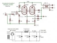
I've redrawn the schematic.
Do you think it would be better to use other output transformers?
Edcor has a GXSE 15 -2.5k, available with 4 ohm, 6 ohm and 8 ohm secondary. I am considering the 6 ohm. Would you advise using these instead of the Transcendars I have?
Thank you again for your help.
I've redrawn the schematic.
Do you think it would be better to use other output transformers?
Edcor has a GXSE 15 -2.5k, available with 4 ohm, 6 ohm and 8 ohm secondary. I am considering the 6 ohm. Would you advise using these instead of the Transcendars I have?
Thank you again for your help.
Attachments
I have a couple of questions about this proposed circuit.
First, regarding the OPT pri:sec impedances. Since the plate-grid local negative feedback reduces the output tubes' plate impedance to down in the triode range, does the OPT primary:secondary impedance make that huge of a difference? I'm thinking that with triode operation of the output tubes, the exact primary impedance becomes less of an issue than with straight pentode operation. Generally speaking, a lower primary impedance allows the output stage to deliver a bit higher power output, but with higher harmonic distortion. A higher primary impedance (relative to the load) reduces both the possible output power and the harmonic distortion present in the output signal. Does something similar to that exist with this 'Schade' plate-grid negative feedback arrangement?
Second, I think the Sovtek 5881WXT (which I think is a repackaged 6P3C-E) is a very different beast from the original USA-made 5881 (6L6WGB). The Sovtek 5881 is very robust, probably good for 30W Pdiss, similar to the later USA-made 6L6GC. However, you'll notice that the Sovtek 5881 (6P3C-E) biases up very differently from any US-made 6L6 type. I've actually found that you can drop a Sovtek 5881 in place of an EL34 in a cathode-biased output circuit and the two will bias up nearly identically. However if I drop in a US-made 6L6GC into that same circuit, the 6L6GC will draw significantly more plate current. That tells me the Sovtek 5881 is very different from any US-made 6L6 type. MJ Koster's choice of 5881WXT may have been deliberate, and not meant to be any other 6L6 type in that particular circuit. I'm sure you could increase the value of the 1k cathode bias resistor and get the circuit to work with a 6L6GC or even an old American 5881 (6L6WGB).
This might explain the situation better.
Sovtek 5881 WXT | 6l6 WGC | 6Π3C-E Tube Guide by Jay Skyler
I'm not sure if that's all 100% accurate, but it agrees with my experience with these tube types.
ziffel,
You should measure the DCR of the primary and secondary of the transformers that you have. That way you can calculate the approximate insertion loss of the transformer at mid frequencies.
You ought to try using the transformers you have first. See how they sound, and how much power you get.
If you are going to have to cut holes or drill holes in the chassis to use the transformer, and a different transformer will not be the same size, holes, spacing, etc., then you might find a way to hook them up before you cut the chassis holes (but be sure to ground the transformer frame for safety reasons).
I once had a new transformer that had its primary shorted to the frame; that could have been a 'shocking' event, if I did not have the frame grounded (you might not see those shorts with an Ohmmeter, but could happen when you apply B+).
Some speaker impedances are lower than you think. i.e. I have some 8 Ohm speakers that are 6 Ohms at some frequencies; and some 4 Ohm speakers have 21/2 Ohms at some frequencies. Consider your speakers actual impedances at different frequencies, especially if you are going to purchase an output transformer that only has a single impedance output tap.
Last edited:
In Triode Mode, the 6W6 plate/screen is rated up to 330V.
But you will not be able to run as much current at 330V as you can at 225V.
As a result of the lower current, the plate resistance in Triode mode will be higher at 330V plate/screen to cathode versus the plate resistance in Triode mode at 225V plate/screen to cathode.
Two Parallel 6W6GTs will be about 800 Ohms. You might try a transformer with 3 times that - a 3,200 Ohm primary. The 22 x 2mA = 44mA, and 30V self bias, with the u = 6.2 should work together there quite well.
The B+ should be:
225V + 30V self bias + (44mA x the DCR of the 3,200 Ohm primary = X volts drop).
Measure the primary DCR, and calculate the total B+ voltage you need.
If you want to use triode mode:
You can do without the Shade feedback resistor. And you can use a triode input tube instead of the MOSFET, with a 450V or 900V IXYS current source in the input tube plate.
Then you can use RC (coupling cap from the driver plate, resistor to ground) connecting to the two 6W6GT grid stopper resistors.
If you want to use triode mode and the Shade feedback with the MOSFET, I think you may have to change the feedback resistor.
There is so much less gain in triode mode, and the open loop to closed loop ratio will not be the same as in Pentode mode.
Last edited:
I do not know how I did it, but on post #9, I talked about what happens when you use a 5k:8Ohm transformer to act as as a 4K:4 Ohm transformer.
I meant 2.5k:4 Ohm, not 4K:4 Ohm.
Using a 5K:8 transformer as a 2.5k:4 transformer will have 2 times the loss caused by DCR of the primary and secondary.
At this hour, not a later hour, I seem to be able to type 2.5k:4. Sorry.
I meant 2.5k:4 Ohm, not 4K:4 Ohm.
Using a 5K:8 transformer as a 2.5k:4 transformer will have 2 times the loss caused by DCR of the primary and secondary.
At this hour, not a later hour, I seem to be able to type 2.5k:4. Sorry.
Last edited:
How's the tempco of the input stage? Just a minute shift in Iq will give large shift in grid voltage...?
Also, it doesnt seem to me the input stage will ever drive the output tubes even close to max, the available symmertic voltage swing is so much less than the tube's cathode bias... ? Is that intentional so the amplifier never clips on the tube output but rather on the FET input? Someone prefers SS clip to vacuum clip?
Also, it doesnt seem to me the input stage will ever drive the output tubes even close to max, the available symmertic voltage swing is so much less than the tube's cathode bias... ? Is that intentional so the amplifier never clips on the tube output but rather on the FET input? Someone prefers SS clip to vacuum clip?
SemperFi,
I did not even question the MOSFET input stage. I was only looking at the output stage.
That takes me back to my idea of using a triode tube for the input stage, and RC coupling.
Can't get much simpler than that. And with a current source in the plate of the input tube, it is very linear (maybe about as linear as the output stage, and so some of the 2nd harmonic distortion is partially cancelled).
For a 30V self biased output tube, there needs to be +/- 30V from the driver for full output.
It is true that clipping (in the cut-off direction) of a single ended output stage causes the amp to loose control of the woofer cone, etc.
But for anybody that does not like the sound of hard clipping or loss of woofer control, just do what I do. Either turn the volume down, or hook up a more powerful amplifier.
Last edited:
Turn down the volume?!?! Never even concidered :-O
Other than that I agree with you on the triode and RC coupling.
Back to the first post it appears as if the original ckt (Koster's with 6L6) works...So has the circuit inventor created a version with some feedback to stabilize the bias? Or has this circuit never really worked? Or is the tempco in real life not actually a problem and the amplifier works well enough as a very simple circuit, accepting limited drive on the grids?
Hi 6A3sUMMER and SemperFi,
I keep reading that a pentode run with Schade feedback show plate resistance similar to that of a triode, that why I referred to the GE triode specs for the 6W6GT.
Your wrote:
"Two Parallel 6W6GTs will be about 800 Ohms. You might try a transformer with 3 times that - a 3,200 Ohm primary."
Would that be loading at 2400 ohms? Or do I want to load them at 4 times plate resistance?
I could have simply used a circuit with a fairly standard tube input RC to triode output, or even adapted the RH-EL84 circuits. Instead, I want to stick with Koster's topology because it seem so novel. I like the 6W6GT so much that I really don't want to hear the influence of any other tubes.
Regarding having +9v on the grids? What would be a better value? +30v? Koster's 6L6GC is running +55 at the grid and +70 at the cathode. I have included a picture of his circuit.
Thank you for your help.
Attachments
Last edited:
- Status
- This old topic is closed. If you want to reopen this topic, contact a moderator using the "Report Post" button.
- Home
- Amplifiers
- Tubes / Valves
- Schematic Critique – Micahel J Koster adapted for 6W6GT in PSE