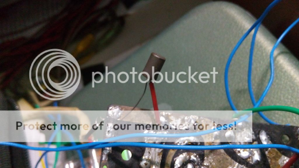
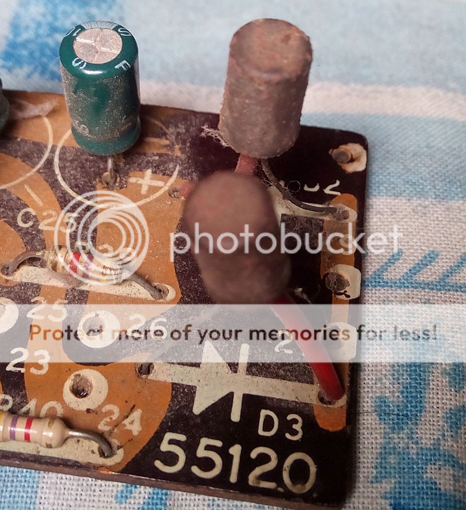
I have came across a very strange looking diode during the restoration of HMV STEREO 666 Record Player. The machine is 40 years old, the diode of interest also has the same age. The marking of the Diode became very faint due to its age. After a great trial I can read the marking as 'BEL OR23'. A strange nomenclature. I could not get any explanation of this name, also could not find any datasheet of this component. I am assuming it as a diode because the silk screen layer of the PCB where the diode was fitted denotes it as a diode and I know that this component was company fitted.
The circuit where the diodes were fitted is a Sound Level Monitoring Circuit, where 3V light bulb glow according to the sound output level of the amplifier. Lights does not glow in its full capacity if these diodes are being used. The circuit works, but the bulbs lack brightness, even in the 100% volume.
Preliminary checking of this component with digital multi-meter (assuming it as a diode) reveals the following results:
Diode Name = OR23
Forward Bias Voltage (Vf) @1mA = 168 mV
Forward Resistance = 900 Kilo-ohm
Reverse Resistance = 900 Kilo-ohm
Maximum Current Handled (I-max) = 1A (assumed from the study of circuit schematic)
I am attaching two pictures of the diode here......
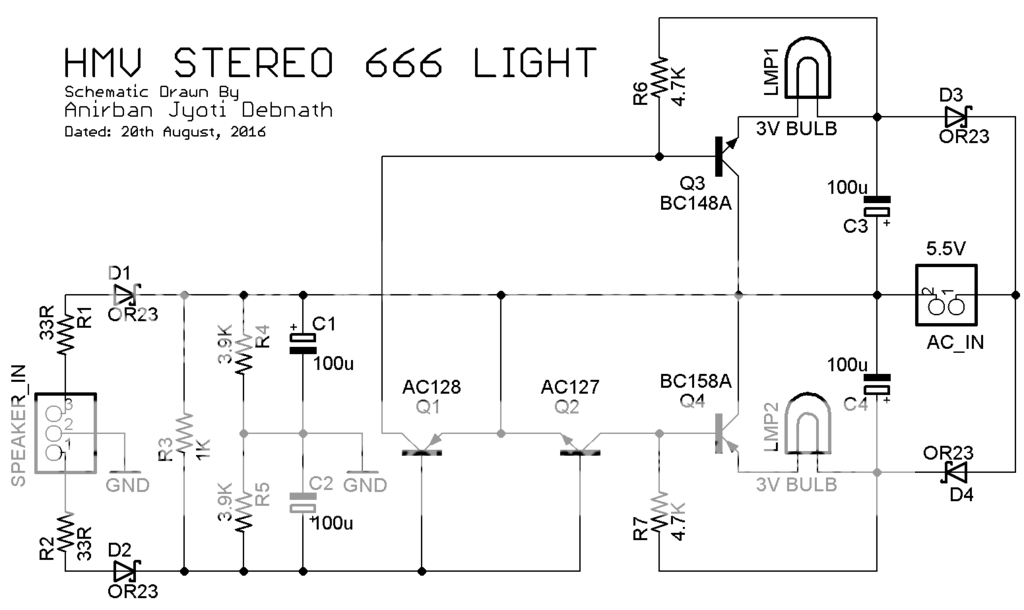
Here is the schematic diagram of the circuit where the diodes were used. I have shown the diodes as Schottky Diode in the schematic
My questions are as follows -
1. If it is a diode, then is it in healthy condition? (the circuit where the diode is attached is operating at its sub optimal condition, same reading of forward and reverse resistance confused me)
2. If it is a diode, is there any replacement can be suggested keeping the specification in mind? (it will be good if a Schottky Diode can replace this diode)
3. If it is not a diode then what is it and what can be the probable replacement of it?
The circuit where the diodes were fitted is a Sound Level Monitoring Circuit, where 3V light bulb glow according to the sound output level of the amplifier. Lights does not glow in its full capacity if these diodes are being used. The circuit works, but the bulbs lack brightness, even in the 100% volume.
Preliminary checking of this component with digital multi-meter (assuming it as a diode) reveals the following results:
Diode Name = OR23
Forward Bias Voltage (Vf) @1mA = 168 mV
Forward Resistance = 900 Kilo-ohm
Reverse Resistance = 900 Kilo-ohm
Maximum Current Handled (I-max) = 1A (assumed from the study of circuit schematic)
I am attaching two pictures of the diode here......
Here is the schematic diagram of the circuit where the diodes were used. I have shown the diodes as Schottky Diode in the schematic
My questions are as follows -
1. If it is a diode, then is it in healthy condition? (the circuit where the diode is attached is operating at its sub optimal condition, same reading of forward and reverse resistance confused me)
2. If it is a diode, is there any replacement can be suggested keeping the specification in mind? (it will be good if a Schottky Diode can replace this diode)
3. If it is not a diode then what is it and what can be the probable replacement of it?
i would think ant rectifier diode would do OK for D3 and D4. I would use 1n4001 (4002, 4004 4007) in this spot.
The speaker in line seems a bit more interesting.
Question: Are you really sure that that schematic is right - as drawn you kind of need to assume the "AC In" is floating relative to the GND net. If not, there will be some interesting currents running around.
Assuming a floating "AC In"...
The circuit seems to detect differential POSITIVE going input between the stereo inputs. How hard the lights will be turned on will be entirely dependent upon how different the two channel inputs are.
The circuit should work with pretty much any diode. The venerable 1n914 / 1n4148 would work fine.
I would expect the lights to be kind of pretty, but kind of "twee" and not expect that mush meaningful from them.
In your diagram D3 and D4 are used as simple power supply rectifiers and so any generic silicon (yours will be germanium by the look of them) will be OK. With 5.5 vac applied you should be getting around 7.5 volts DC across C3 and C4.
D1 and D2 MUST be germanium because the circuit replies on germaniums low forward voltage to minimise losses. The same applies to Q1 and Q2. They must be germanium as well.
Practical point... D3 and D4 will be somewhat 'lossy' and this property gives the circuit a self limiting action. You might find that adding a series resistor to each diode helps maximise the life of both the bulbs and also C3 and C4. Maybe try something like 10 ohms initially.
I would dare to say they are germanium diodes based on the surrounding circuit and the use of to1 packaging. Likely in the 25 volt 500mA range. Testing with a modern multimeter may not give accurate readings due to rather low test currents. It is possible the leakage has grown considerable over the years, decreasing their ability to rectify properly. Since they do not perform a special function in this circuit, a schottky should work fine as a replacement.
i would think ant rectifier diode would do OK for D3 and D4. I would use 1n4001 (4002, 4004 4007) in this spot.
The speaker in line seems a bit more interesting.
Question: Are you really sure that that schematic is right - as drawn you kind of need to assume the "AC In" is floating relative to the GND net. If not, there will be some interesting currents running around.
Assuming a floating "AC In"...
The circuit seems to detect differential POSITIVE going input between the stereo inputs. How hard the lights will be turned on will be entirely dependent upon how different the two channel inputs are.
The circuit should work with pretty much any diode. The venerable 1n914 / 1n4148 would work fine.
I would expect the lights to be kind of pretty, but kind of "twee" and not expect that mush meaningful from them.
The schematic is 100% correct. I have simulated the circuit, and it work fine. I can provide the simulation file by which it can be simulated online. Tell me if you need it.
I have tested 1N4007 and 1N4148 in all possibilities, The outcome is more decreased sensitivity of the lights, brightness was severely decreased. The probable reason is both of the diode's Forward Biasing Voltage (Vf) is somewhat between 500-600 mV @1mA current. And this diode of interest is showing 165 mV in similar test condition. What I understood from the schematic that current should flow smoothly across the diodes to keep the circuit functional, and for this, the diodes must be of fast switching type having low Vf.....
BDW, my question was, is there any possible substituent (part number needed) for this diode?
In your diagram D3 and D4 are used as simple power supply rectifiers and so any generic silicon (yours will be germanium by the look of them) will be OK. With 5.5 vac applied you should be getting around 7.5 volts DC across C3 and C4.
Please note that polarity of D3 and D4 is opposite to each other. Actually this design turn on Q3 and Q4 in an alternative way. this done due to show the transient responses coming from each channel. And this design needs fast switching of the both transistors. I have used 1N4007, they did not gave me desired result, they decreased the sensitivity of the bulbs....
D1 and D2 MUST be germanium because the circuit replies on germaniums low forward voltage to minimise losses. The same applies to Q1 and Q2. They must be germanium as well.
Yes, Q1 and Q2 are germaniums, they are AC127/AC128 complementary pairs, I have mentioned them in the schematic.....
Practical point... D3 and D4 will be somewhat 'lossy' and this property gives the circuit a self limiting action. You might find that adding a series resistor to each diode helps maximise the life of both the bulbs and also C3 and C4. Maybe try something like 10 ohms initially.
Buddy, I need to make the circuit functional at its optimum at first, after that I will think about the life of the El-cheapo 3V light bulbs...
According to your schematic the bulbs indicate witch channel is the loudest.Only the loudest light up, equal = no lightThe circuit where the diodes were fitted is a Sound Level Monitoring Circuit, where 3V light bulb glow according to the sound output level of the amplifier. Lights does not glow in its full capacity if these diodes are being used. The circuit works, but the bulbs lack brightness, even in the 100% volume.

Those two values don't go togetherForward Bias Voltage (Vf) @1mA = 168 mV
Forward Resistance = 900 Kilo-ohm
1. If it is a diode, then is it in healthy condition? (the circuit where the diode is attached is operating at its sub optimal condition, same reading of forward and reverse resistance confused me)
 Doesn't look healty.
Perhaps a Schottky will do or else goldpoint Ge diodes like AA143 or AAZ17.2. If it is a diode, is there any replacement can be suggested keeping the specification in mind? (it will be good if a Schottky Diode can replace this diode)
And, like Mooly said, D3/D4 not critical but Q1 and Q2 Ge transistors.
Mona
Looks like a shockley diode.
Yes, these diodes looks like commercially available Shockley Diodes. But shockley diodes take time to switch on, then remain there, then suddenly switches off if the voltage across it decrease below a certain level, and remain in switch off condition until the threshold switch on voltage is applied. The whole process needs time. The circuit needs fast switching of these diodes....
Those are Germanium diodes, used to rectify low voltage audio signals and turn lamps on as crude VU meters or levelindicators.
If it works, leave them as is.
They are not meant to illuminate the room so don´t worry if they seem weak for that use , they are there to show the amp is passing audio.
Shining bright means in a few months they will die, weak they can last many years.
Just as a reference, but do NOT replace the originals if they work, they are similar to old classics 1N34 or OA81 ; don´t know what modern Ge diodes are available.
If it works, leave them as is.
They are not meant to illuminate the room so don´t worry if they seem weak for that use
, they are there to show the amp is passing audio.Shining bright means in a few months they will die, weak they can last many years.
Just as a reference, but do NOT replace the originals if they work, they are similar to old classics 1N34 or OA81 ; don´t know what modern Ge diodes are available.
Those are Germanium diodes, used to rectify low voltage audio signals and turn lamps on as crude VU meters or levelindicators.
If it works, leave them as is.
They are not meant to illuminate the room so don´t worry if they seem weak for that use
Shining bright means in a few months they will die, weak they can last many years.
Just as a reference, but do NOT replace the originals if they work, they are similar to old classics 1N34 or OA81 ; don´t know what modern Ge diodes are available.
The lamps glow weakly if the speakers are not attached to the amplifier. If I attach the speakers then no glow. Every components of the circuit is fine, I have double checked them, except those diodes are suspicious.........
I would dare to say they are germanium diodes based on the surrounding circuit and the use of to1 packaging. Likely in the 25 volt 500mA range. Testing with a modern multimeter may not give accurate readings due to rather low test currents. It is possible the leakage has grown considerable over the years, decreasing their ability to rectify properly. Since they do not perform a special function in this circuit, a schottky should work fine as a replacement.
You told exactly the same points I was thinking about. Can you suggest some schottky diodes for this purpose?
They wont be Shokley diodes. The fact that all four are 'OR23' pretty much confirms they are standard germanium devices. D3 and D4 as previously mentioned are simply producing a + 7.5 and -7.5 volt rail from the 5.5 volt AC input.
7.5 volts rail, 3 volts bulbs ! That possibly suggests a highish impedance of the supply such that the bulbs can flash brightly (via the stored energy in the reservoir caps) and then the voltage falls away.
These circuits will be critically dependent on the correct bulb being fitted and 'optimum' performance may seem pretty poor by todays expectations. It was all cutting edge back then though
Perhaps a Schottky will do or else goldpoint Ge diodes like AA143 or AAZ17.
Can you suggest me some Schottky Diodes for this?
D3 and D4 as previously mentioned are simply producing a + 7.5 and -7.5 volt rail from the 5.5 volt AC input.
7.5 volts rail, 3 volts bulbs ! That possibly suggests a highish impedance of the supply such that the bulbs can flash brightly (via the stored energy in the reservoir caps) and then the voltage falls away.
Presently 3V bulb is enlighting dimly in this circuit. The original bulbs were missing from the player. At first I have to make the circuit 'optimum', after that I can easily change the bulb with a 6V lamp.
These circuits will be critically dependent on the correct bulb being fitted and 'optimum' performance may seem pretty poor by todays expectations. It was all cutting edge back then though
Actually I am restoring this 40 years old machine. I am trying to restore the machine in its original state as much as I can. Amplifier and the mechanical parts are done for this machine, the only remaining part is this small Level Monitoring Board. It will be very helpful if a suitable diode replacement (part number) is suggested.....
The restoration story is available in the following link
Restoration of HMV STEREO 666 (1976)
BAT46 or BAT48. Cheap and cheerful and readily available. Shottkys wont do for the input diodes though.
There are some GY102's on ebay:
20 of GY102 germanium rectifier-diode 75V/0,1A RFT | eBay
Can't really see those being faked.
There are some GY102's on ebay:
20 of GY102 germanium rectifier-diode 75V/0,1A RFT | eBay
Can't really see those being faked.
BEL was an Indian valve (and semiconductor?) manufacturer. They had some connections wth Philips, so it is quite likely that the 0R23 was based on a Philips diode. It may even have been just a modified transistor - it is in a transistor can.
Can you tell me any information about this BEL OR23?
I have came across a very strange looking diode during the restoration of HMV STEREO 666 Record Player. The machine is 40 years old, the diode of interest also has the same age. The marking of the Diode became very faint due to its age. After a great trial I can read the marking as 'BEL OR23'. A strange nomenclature. I could not get any explanation of this name, also could not find any datasheet of this component. I am assuming it as a diode because the silk screen layer of the PCB where the diode was fitted denotes it as a diode and I know that this component was company fitted.
The circuit where the diodes were fitted is a Sound Level Monitoring Circuit, where 3V light bulb glow according to the sound output level of the amplifier. Lights does not glow in its full capacity if these diodes are being used. The circuit works, but the bulbs lack brightness, even in the 100% volume.
Preliminary checking of this component with digital multi-meter (assuming it as a diode) reveals the following results:
Diode Name = OR23
Forward Bias Voltage (Vf) @1mA = 168 mV
Forward Resistance = 900 Kilo-ohm
Reverse Resistance = 900 Kilo-ohm
Maximum Current Handled (I-max) = 1A (assumed from the study of circuit schematic)
I am attaching two pictures of the diode here......
Here is the schematic diagram of the circuit where the diodes were used. I have shown the diodes as Schottky Diode in the schematic
My questions are as follows -
1. If it is a diode, then is it in healthy condition? (the circuit where the diode is attached is operating at its sub optimal condition, same reading of forward and reverse resistance confused me)
2. If it is a diode, is there any replacement can be suggested keeping the specification in mind? (it will be good if a Schottky Diode can replace this diode)
3. If it is not a diode then what is it and what can be the probable replacement of it?
An OR23 is a germanium diode (as opposed to today's silicon diodes). Germanium diodes have a much lower forward voltage, like 200mV in contrast with silicon diodes that have a nominal 600mV forward threshold.
Germanium diodes were often used in meter rectifiers as in your amp; the low forward threshold makes the meter just a bit more accurate at low levels.
I don't think you can still get them, so you would be looking for any small-signal low threshold diode. Small schottkys probably come closest, but check with Google - there may be some dedicated special low threshold diodes somewhere.
Jan
- Status
- This old topic is closed. If you want to reopen this topic, contact a moderator using the "Report Post" button.
- Home
- Design & Build
- Parts
- Any Replacament for this Diode?