Hi,
Ready to embark on my next amplifier build and chose this one from eBay:
PR-800 Class A /AB Professional power amplifier board ?no heatatsink) CL135 | eBay
Would be good to hear from anyone who has built/bought previously and has any words of wisdom before I throw the power switch") . Or will I be out there my own again, path-finding another classic good amp design (Locanthi-T topology?) that has numerous opportunities for component/circuit tweaks that might turn it into a half-decent amplifier. I know one thing for sure, I wont be running it at 2.5A quiescent current per channel as I already have a perfectly good toaster in the kitchen
. Or will I be out there my own again, path-finding another classic good amp design (Locanthi-T topology?) that has numerous opportunities for component/circuit tweaks that might turn it into a half-decent amplifier. I know one thing for sure, I wont be running it at 2.5A quiescent current per channel as I already have a perfectly good toaster in the kitchen
Ready to embark on my next amplifier build and chose this one from eBay:
PR-800 Class A /AB Professional power amplifier board ?no heatatsink) CL135 | eBay
Would be good to hear from anyone who has built/bought previously and has any words of wisdom before I throw the power switch
. Or will I be out there my own again, path-finding another classic good amp design (Locanthi-T topology?) that has numerous opportunities for component/circuit tweaks that might turn it into a half-decent amplifier. I know one thing for sure, I wont be running it at 2.5A quiescent current per channel as I already have a perfectly good toaster in the kitchendjk, personal experience or finger-in-the air calculation? Cant find any near schematics or "pseudo-schematics" out there but the all-transistor, multi-parallel output stage should be fairly easy to sketch up. The huge 10,000uF/rail on-board electrolytic's might be a bit over-kill but would form a useful part of a larger high-current, filtered power supply. Needs a separate ac/dc supply for the pre-amp or bias section though, which is not convenient. I only use 8 ohm speakers and my listening space is not huge but I would be interested to see if this design can deliver a deeper bass response, with my existing gear.
300W into 4ohms requires a maximum output of 49Vpk.
You should be able to get that from a poorly built/designed +-70Vdc fed amplifier.
A really good design/build would probably get a maximum output of around 60Vpk into 4r0 test load.
Check the SOA of the 2sa1943/c5200 @ 70Vce. They are terrible compared to good transistors @ that voltage.
+-10mF (10000uF) is low for a power amplifier, especially one claiming to be 4ohms capable.
I use +-20mF for 8ohms speaker capability and recommend +-40mF for 4ohms capability.
Last edited:
Hi Andrew, I wont dispute your calculations but might take issue with your blanket assumption that this is also a poorly designed amplifier for reasons mentioned. Have you built, tested and listened to it? I am not interested in building a high power "disco" amp but will probably run it conservatively at 55 - 60V supplies. I normally use about 30 mF filter caps in my amplifier builds so we can agree on that, I would RC filter the on-board capacitors from the larger main power supply. Not sure that your SOA concerns are a major issue when you consider there are 4 parallel pairs of output transistors, and they will be moderately biased Class AB. Sure, there are probably much better transistors available but the ones supplied should be good enough.
expect the supply to sag when under load. A volt or two droop when the amplifier is quiescent, another 3V to 10V when under maximum load testing. That gets your Vpk down to 40Vpk to 50Vpk.................. but will probably run it conservatively at 55 - 60V supplies. I normally use about 30 mF filter caps in my amplifier builds so we can agree on that, ...................
You should be concerned about SOA. You need to temperature de-rate as well................Not sure that your SOA concerns are a major issue when you consider there are 4 parallel pairs of output transistors, and they will be moderately biased Class AB. Sure, there are probably much better transistors available but the ones supplied should be good enough.
The 1943/5200 are terrible at the higher voltages. Look at the datasheet and compare to an MJW0281/0301. Both are 150W devices.
@ 70Vce & 25°C, the Toshiba has a rating of ~68W whereas the ONsemi has a rating of ~102W
If you run @ +-55Vdc, then the Toshiba compare much more closely.
I have recommended in the past that for ClassAB, the Toshiba should not be used @ >+-55Vdc. ONsemi and Sanken are more suitable.
Last edited:
Andrew, thanks for elaborating on the importance of SOA and temperature derating. The supplied transistors should perform OK at the nominal +/- 55V supply rail. The amplifier PSU design will hopefully minimise sag and droop. As we know, the amplifier sellers quoted 'head-line' performance figures are more mythical than practical. I will post results (good or bad) but still happy to hear from anyone who has built and tested this module.
That is a more reasonable PSU voltage for the 1943/5200 outputs................ The supplied transistors should perform OK at the nominal +/- 55V supply rail............
Expect 4pr to give around 200W for maximum reliable power.
You should get around 150W to 170W into 8ohms when using a 230:40+40Vac transformer. That transformer gives me +-58.5Vdc, when mains is 240Vac
Do not try to use 4ohms speakers with a 40+40Vac transformer. I recommend a maximum of 35+35Vac for a 4ohms speaker.
PR-800 Class A/AB
A first look at the PR-800 ClassA/AB design and layout revealed some interesting "features"
1) The IPS has MPSA42/2N5551 NPN Darlington input pair with a 2N5551 cascode in each collector arm.
2) In spite of 2 x 4700uF/rail PSU capacitors on-board next to the connection terminal block, there are no other localised decoupling electrolytics elsewhere.
3) There are no base stopper resistors on the output Toshiba power transistors.
4) No output Zobel network.
5) A large number of components are used in a SOA/fault current output protection circuit which has a latching SCR device, requiring a separate 6 - 15 VAC supply.
I have not come across a Darlington IPS before and there seems to be very little documentation about them - not a great start. I would be keen to remove/disable the protection circuit to avoid the need for a separate transformer or a low voltage winding on the mains transformer. As discussed, I will be using +/- 55 V DC supplies so the circuit is probably an overkill. The other things are easy to resolve by hacking a few pcb tracks and adding additional components but beginning to wonder if this is a good audio design to start with. Anyone out there with any relevant experience with this particular amplifier?
Attachments
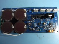
PR-800 Class A/AB unwrapped
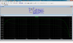
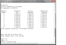
Before I started hacking the PR-800 boards, I thought it would be a good idea to sketch the circuit design from the board to review the design and map how the components were interconnected. At the same time, I learned to use LTspice as this would be useful to check the performance of the original PR-800 and any subsequent design changes I implemented. The performance "specifications" provided by the eBay seller listing were incomplete with no test conditions against any of the performance figures. I used LTspice to try simulate the Harmonic Distortion and Frequency response measurements against the claimed performance figures:
Harmonic Distortion: <0.01 10W/8 Ohm
Frequency Response: 1Hz - 160KHz (-3dB)
In my simulated amplifier, I set the supply rails to +/- 45 VDC and adjusted the input 1 KHz test signal to deliver 10W into 8 Ohm resistive load. I adjusted the output stage bias to the optimum class AB, approx. 120mA per transistor pair (4 parallel pairs) which should have given low distortion. The results screenshots are attached and the simulated performance figures:
Harmonic Distortion: <0.065% 10W/8 Ohm (10th order?) 10KHz bandwidth
Frequency Response: 1Hz - 500KHz (-3dB)
Unless I am using inaccurate component models or my understanding of LTspice is not up to scratch (very likely), these performance figures seem way off. If they are accurate, at least I know my starting point
Before I started hacking the PR-800 boards, I thought it would be a good idea to sketch the circuit design from the board to review the design and map how the components were interconnected. At the same time, I learned to use LTspice as this would be useful to check the performance of the original PR-800 and any subsequent design changes I implemented. The performance "specifications" provided by the eBay seller listing were incomplete with no test conditions against any of the performance figures. I used LTspice to try simulate the Harmonic Distortion and Frequency response measurements against the claimed performance figures:
Harmonic Distortion: <0.01 10W/8 Ohm
Frequency Response: 1Hz - 160KHz (-3dB)
In my simulated amplifier, I set the supply rails to +/- 45 VDC and adjusted the input 1 KHz test signal to deliver 10W into 8 Ohm resistive load. I adjusted the output stage bias to the optimum class AB, approx. 120mA per transistor pair (4 parallel pairs) which should have given low distortion. The results screenshots are attached and the simulated performance figures:
Harmonic Distortion: <0.065% 10W/8 Ohm (10th order?) 10KHz bandwidth
Frequency Response: 1Hz - 500KHz (-3dB)
Unless I am using inaccurate component models or my understanding of LTspice is not up to scratch (very likely
), these performance figures seem way off. If they are accurate, at least I know my starting pointAttachments
Last edited:
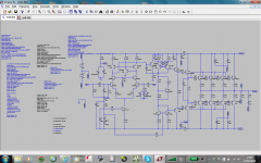
Hi Ian, that was deliberate because I didn't want to publish the circuit detail on-line. Though its origins are unknown and it may well have been cobbled together from other published designs, I observe the original designers copyright. Besides, I know if I publish the .asc simulation file on this forum, every man and his dog will "re-design" it for me thus denying me the opportunity to teach myself. With Cordell and D. Self amplifier volumes at the ready and the excellent information available on this forum, I should be able to tweak the design within the constraints of the existing layout and probably improve performance before I build into my amplifier case. Note, i have not done any actual testing of the amplifier performance and my LTspice simulation could well be wrong but its somewhat irrelevant since I will be hacking the existing circuit anyway.
As a result of investigating the circuit design, I discovered that the requirement for the additional 6 - 15 VAC supply was to provide separate DC power rail for a current source for the LTP current bias transistor, not the protection circuit as previously thought. So, there is clearly opportunity to change this and avoid the need for a separate transformer winding or transformer. The protection circuit is different in that it is not the usual dynamic V/I limiter but an SCR-triggered design which shuts off the LTP bias, presumably if an excessive current flows through the output stage first transistor pair. I assume you would reset the amplifier by switching OFF/ON if that condition was reached. Not sure if I want/need that kind of "protection" as its of limited use anyway. The other thing the LTspice simulation flagged up was that output DC offset was likely to be high so this could be minimised by matching transistor pairs or with some adjustment trimmer.
. With Cordell and D. Self amplifier volumes at the ready and the excellent information available on this forum, I should be able to tweak the design within the constraints of the existing layout and probably improve performance before I build into my amplifier case. Note, i have not done any actual testing of the amplifier performance and my LTspice simulation could well be wrong but its somewhat irrelevant since I will be hacking the existing circuit anyway.As a result of investigating the circuit design, I discovered that the requirement for the additional 6 - 15 VAC supply was to provide separate DC power rail for a current source for the LTP current bias transistor, not the protection circuit as previously thought. So, there is clearly opportunity to change this and avoid the need for a separate transformer winding or transformer. The protection circuit is different in that it is not the usual dynamic V/I limiter but an SCR-triggered design which shuts off the LTP bias, presumably if an excessive current flows through the output stage first transistor pair. I assume you would reset the amplifier by switching OFF/ON if that condition was reached. Not sure if I want/need that kind of "protection" as its of limited use anyway. The other thing the LTspice simulation flagged up was that output DC offset was likely to be high so this could be minimised by matching transistor pairs or with some adjustment trimmer.
Last edited:
I managed to get up to speed with LTspice and spent more hours than was really healthy tweaking the original PR-800 Class A/AB design into something much better. I was very grateful to astx and other diyaudio members for their brilliant work on this thread:
http://www.diyaudio.com/forums/soli...ormance-class-ab-power-amp-200w8r-400w4r.html
which was basically a master-class tutorial in how to use LTspice to design, test and evaluate a class AB amplifier. This work was even more relevant to mine because the PR-800 circuit design was quite similar and could be modified fairly easily using the same configuration in the 2-stage class AB amplifier.
But first, I revisited the original PR-800 design to re-evaluate using the same DC supplies and input signal conditions as the simulated new design. The results were much worse than before because now it appeared that the PR-800 displayed asymmetrical clipping at +46/-34V levels on +/- 59V DC supplies, probably due to the protection circuit or bad biasing. I had not seen that during previous simulations at 10W into 8 ohm. It didn't look good, that protection circuit really had to go
Since the new design is now quite different from the original PR-800, I have no issues with sharing the LTspice files and component models for the new amplifier now renamed to SAB-800. I copied over as much of the 2-stage class AB design as I could bearing in mind that I was implementing this on an existing amplifier layout, so could not make it identical. Nevertheless, from the results, the THD figures are now orders of magnitude less than before and there is no evidence of premature asymmetrical clipping behaviour. The biggest reduction in simulated THD figures was when I copied over the Q9/Q12/Q13 VAS driver stage (Q8/Q9/Q25 on SAB-800). Of course, these are only LTspice simulated performance figures so actual implementation could be significantly different. There may be further component tweaks to improve performance even more but the issue here is that I will always be constrained by implementing the final circuit on the existing PR-800 amplifier board.
http://www.diyaudio.com/forums/soli...ormance-class-ab-power-amp-200w8r-400w4r.html
which was basically a master-class tutorial in how to use LTspice to design, test and evaluate a class AB amplifier. This work was even more relevant to mine because the PR-800 circuit design was quite similar and could be modified fairly easily using the same configuration in the 2-stage class AB amplifier.
But first, I revisited the original PR-800 design to re-evaluate using the same DC supplies and input signal conditions as the simulated new design. The results were much worse than before because now it appeared that the PR-800 displayed asymmetrical clipping at +46/-34V levels on +/- 59V DC supplies, probably due to the protection circuit or bad biasing. I had not seen that during previous simulations at 10W into 8 ohm. It didn't look good, that protection circuit really had to go
Since the new design is now quite different from the original PR-800, I have no issues with sharing the LTspice files and component models for the new amplifier now renamed to SAB-800
. I copied over as much of the 2-stage class AB design as I could bearing in mind that I was implementing this on an existing amplifier layout, so could not make it identical. Nevertheless, from the results, the THD figures are now orders of magnitude less than before and there is no evidence of premature asymmetrical clipping behaviour. The biggest reduction in simulated THD figures was when I copied over the Q9/Q12/Q13 VAS driver stage (Q8/Q9/Q25 on SAB-800). Of course, these are only LTspice simulated performance figures so actual implementation could be significantly different. There may be further component tweaks to improve performance even more but the issue here is that I will always be constrained by implementing the final circuit on the existing PR-800 amplifier board.Attachments
Thanks Andrew, don't think I can take much credit for other members hard work but it does show that it might be possible to make a "silk purse out of a sow's ear". A definite thumbs-up for cut'n'paste audio design. All I need to do now is implement onto the PR-800 board. Luckily, by removing the dubious protection circuit, I have plenty of free PTH for the extra components and have also become very adept with my Dremel. It wont look pretty but you don't listen with your eyes, after all.
. A definite thumbs-up for cut'n'paste audio design. All I need to do now is implement onto the PR-800 board. Luckily, by removing the dubious protection circuit, I have plenty of free PTH for the extra components and have also become very adept with my Dremel. It wont look pretty but you don't listen with your eyes, after all.Dear roclite,
increase OPS bias to oliver point and you will get even better distortion figures. Currently you have biased one OPS bjt pair with about 25mA - increase it to e.g. 90mA and you will get better distortion figures (asc file: reduce R13 from 655R to 625R). If you want to keep lower BIAS current you have to increase the emitter resistors up to 0.47R.
Try to add "TianProbe()" parts to check the NFB loop stability.
Have fun, Toni
Hi Toni
Thanks for your advice and many thanks for sharing your 2 Stage Class AB amplifier design, I learned a lot reading about the design steps you took during the development.
I keep the OPS bias quite low to reduce quiescent power dissipation in the output stage and driver transistors, mostly TO-92. The SAB-800 boards will be installed into an old amplifier case re-using switches, output terminals, heatsinks etc so usually the heatsinks are not optimum size. Replacing the 0.22R emitter resistors is likely to damage the boards so I would keep as is. Apart from that, there are 16 of them. I will try the Tianprobe before I implement the changes. I did notice what looks like a bit of frequency ripple/instability on the square-wave trailing edge that meant I had to increase my base stopper resistors from 4.7 to 15 Ohm, probably higher than I would like.
Thanks for your advice and many thanks for sharing your 2 Stage Class AB amplifier design, I learned a lot reading about the design steps you took during the development.
I keep the OPS bias quite low to reduce quiescent power dissipation in the output stage and driver transistors, mostly TO-92. The SAB-800 boards will be installed into an old amplifier case re-using switches, output terminals, heatsinks etc so usually the heatsinks are not optimum size. Replacing the 0.22R emitter resistors is likely to damage the boards so I would keep as is. Apart from that, there are 16 of them
. I will try the Tianprobe before I implement the changes. I did notice what looks like a bit of frequency ripple/instability on the square-wave trailing edge that meant I had to increase my base stopper resistors from 4.7 to 15 Ohm, probably higher than I would like.Hey, you guys brings me hope!! :-D A Year ago i did buy 14 PR-800 Amplifiers to drive by mini-disco, but haves big problems with the PR-800 in the Subwoofers. Have 2 PR-800 in bridge for each driver, but it goes in protection-mode very often :-/ Not funny when you are on a job... Had tryed to fix the problem by putting a small-capasitor on each input and measured and changed the bridging circuit, but it seems it is the protection-part on the PR-800 Boards there just is to protective :-S On the final output i uses at external protection-board and it is fine. So i vill be so thankful if you can help me, or guide me to set the inbuilt protection circuit out of function! (Sorry Im from Denmark not good to English) Please help
(Sorry Im from Denmark not good to English) Please help - Home
- Amplifiers
- Solid State
- PR-800 ClassA/AB Amplifier Kit