Hi.
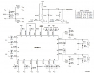
Can you please help me to repair Behringer Subwoofer (B1200D Pro). I didn't find the schematic. I used TDA8954 datasheet as a reference. I attached the schematic from the datasheet.
I replaced the chip but the subwoofer stayed silent. After checking I found a broken leg of Llc1 (restored it) and strange value of Rvssa (150 ohm instead of 10, changed it).
Now all voltages seems ok (+-37V), but OUT1 is -20V, OUT2 is -12V.
Each measurement was done in seconds (less then 5 sec I suppose), because TDA8954 worms up greatly, and I had to remove it from the heatsink to be able to measure.
Can I check something more?
Is the chip dead again?
Thanks.
Attachments
With no load VDD and VSS are ok (+-37V). There is no oscillation on pins 10 and 14 (just constant negative voltage: -20V and -12V...The first thing to do is place a heatsink on the ic. With no load,VDD and VSS OK? Does it oscillate pin 10 and pin 14? If not it is probably damaged.
Ok, it seems it is damaged. What should I check before replacement? How can I find the reason of the damage?
PS: The voltage from Rvssa is applied to VSSA pin of the chip. Before the replacement of Rvssa there was -3V. Can this be the reason of the chip damage?
Thanks.
Last edited:
Is there some technique for testing without expensive equipment?VSSA is the driver supply internally. I should think the chip just died, either of natural causes or overload. Make sure the Boot Strap capacitors are not leaky!
I have an oscilloscope with 10MHz bandwidth. Is it enough? Where I can get the information on the techniques needed for testing D class amps? What about the leakage?It is class D and requires at least a reasonable oscilloscope otherwise it is all guess work.
If my questions are too obvious for D class amps builders please give me the reference where I can learn the theory.
Thanks.
But what should I check before turning on an amp after changing the amp chip (or for example making the amp from scratch). I ask because I changed TDA8954, turned the amp on, and the chip has died, and I even don't know why. Two possible reasons are mentioned in my first post...A 10MHz oscilloscope is enough for repairing most class D amps. You might also need an ESR meter which is about $15 from EBay to check the capacitors. With some effort you could use the oscilloscope as an ESR meter.
Maybe the -VSSA pin is the most negative pin in the internal IC substrate and because of 150R "initial" value, the voltage here goes less negative than output and this *maybe* have destroyed the chip due some internal parasitic thyristor or bipolar action.
For example, chips like TDA7293 explode if the output -V pin is more negative than pre -V pin.
So *maybe* with all correct values and legs in place, the amplifiers works again.
For example, chips like TDA7293 explode if the output -V pin is more negative than pre -V pin.
So *maybe* with all correct values and legs in place, the amplifiers works again.
But what should I check before turning on an amp after changing the amp chip (or for example making the amp from scratch). I ask because I changed TDA8954, turned the amp on, and the chip has died, and I even don't know why. Two possible reasons are mentioned in my first post...
For such a simple circuit, you can do the following:
-remove (unsolder) the TDA8954 from the circuit
-measure the value of all the components, resistors, capacitors, inductances using a multimeter and an ESR meter
-with a multimeter check all the traces in the circuit:
-the points that are connected by traces have low resistance between them
-those that are not connected, have high resistance between them
-turn on the power without a TDA8954 and measure all the voltages
and compare them with the expected ones
-then solder a good TDA8954 and check the connexions and traces to its pins
-if available, power the circuit from a current limited power source, limiting the current to a value well below what TDA8954 can take
-check that the TDA8954 doesn't heat too much using your finger or a thermometer; if it does, cut the power supply immediately and repeat the steps above
-if it doesn't overheat, then check the voltages to its pins
-if they have the expected values, check for oscillation at the output pins (10 and 14)
If you choose to these steps (or similar ones) you can post here your findings after each step and you'll most likely receive help.
If you decide to rebuild the circuit on the same PCB:
-desolder all the old components
-check the the traces carefully as explained above
-buy new components and check them with a multimeter before soldering them
-solder all the capacitors first and then check them in circuit with a multimeter
-solder all the resistors and then check them in circuit with a multimeter
-solder all the rest (inductances then diodes, transistors) except for the TDA8954
-apply power and check that all the voltages to have the expected values
-solder the TDA8954 and the follow the same steps as above after soldering the IC
Hope this helps and don't hesitate to ask questions.
Last edited:
Thank you for the thorough checking algorithm. I didn't measure the ESRs - I need to buy or make the device. I ordered one more TDA8954. Waiting for the arrival. I managed to obtain correct voltages with the burned chip, except the absence of the oscillations on the output pins (there was constant negative voltage on them).So, did you make any progress repairing your amp ?
By the way, when I changed the chip, I turned the amp via filament lamp, but the amp didn't turn on. It looked like this: the lamp gradually started to glow in full force (it took about a second) then abruptly turned off, then the process repeated. So I excluded it. I suppose such behavior was determined by a switching power supply.
- Status
- This old topic is closed. If you want to reopen this topic, contact a moderator using the "Report Post" button.
- Home
- Amplifiers
- Class D
- Behringer Sub TDA8954 repair