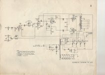
I am working on a Lafayette pa model pa622. The first stage uses a 12ax7 grid leak biased. I read some online about how this arrangement works but am not getting it. Does the cap and grid resistance somehow create a negative voltage? I am not having any problems in relation to this stage but I wan to understand it, thanks, Fred
Attachments
The cap just provides DC blocking. The negative voltage comes from grid current.
People often say that a thermionic diode needs to be forward-biased in order for forward current to flow. This is not true. The heat of the cathode means that some electrons may have enough thermal energy to reach the anode even when it is slightly reverse biased. This is how some types of thermoelectric generator work.
The triode grid acts in place of the anode of the diode. Having a positive voltage on the triode anode increases the effect, by giving the electrons more energy. For a typical triode the grid current can be forward for voltages more positive than around -1.5V to -0.5V. This current sets up a voltage across the 10M resistor, which then tends to reduce the grid current.
The reason this method is used is that it enables the cathode to be directly grounded. This reduced the effect of heater-cathode leakage in the days before DC heaters. It is used for low-level inputs. Large signals (or high source impedance) would create distortion, as the grid current is non-linear.
Notice how usually grid leak bias has very large grid resistor? That is the key. Once cathode is heated, it will start to emit electrons and some is caught by grid electrode. Since the grid now contains electrons, it starts to become more negative compared to cathode which is connected to ground.
If the grid resistor is the usual 100k-1Meg size, those electrons would have escaped from the grid and returned back to ground, causing the grid to revert back to ground potential. However, since the grid resistor is very large (10M), electrons would remain trapped and give you the negative grid bias.
The minuscule negative bias above itself is enough to allow electrons to flow from cathode to plate but just trickles. Interesting thing happens if we drive the grid with some input signal. If somehow the input signal causes grid to become more positive than cathode (positive half of sine wave, perhaps), this will attract more electrons to the grid, trapping more of them and causing even more negative grid potential. Now we have even more electron flow from cathode to plate --> bias current.
So, in a way, the input signal helps to create the bias current itself!
Maybe...just consider the 10M resistor is about equivalent to the usual input resistance of a dvom...so the resistance will be halved by measurement. This is probably enough to change the bias.
Measure plate voltage before and during and see if the g1-k measurement changes the plate voltage...")
cheers,
Douglas
Measure plate voltage before and during and see if the g1-k measurement changes the plate voltage...
cheers,
Douglas
No, that is the situation we need to avoid as it leads to significant distortion.ballpencil said:So, in a way, the input signal helps to create the bias current itself!
DVMs often have 10M resistance on voltage ranges. This will shunt the 10M resistor already in the circuit so you will be seeing the effect of a 5M resistor. You will see some voltage, but probably a bit less than is there without the DVM.jeeptechfred said:Is the negative grid voltage measurable with dvom?
Thanks for the information, when i have the amp back up and running (power tubes were bad and had to order) I am going measure and scope stage with a signal running through it. I am interested in "seeing" the this type of stage on operation. Finding a good discription of how the grid leak bias works is difficult so I appreciate everybody's input
DVMs often have 10M resistance on voltage ranges. This will shunt the 10M resistor already in the circuit so you will be seeing the effect of a 5M resistor. You will see some voltage, but probably a bit less than is there without the DVM.
Hence why with a good millivolt-range meter, I would use a 240 megohm resistor in series with the probe tip. Then just multiply whatever millivolts by 25. The impact of the 250 megohm total impedance is very small on the 10 megohm grid-to-earth tiedown resistor.
GoatGuy
No, that is the situation we need to avoid as it leads to significant distortion.
The way i imagined it, with no input signal and only relying on thermal energy, the negative bias would be small, say, -100 to -200mV. However, once we apply some low amplitude input signal, say, 500mV-peak sinewave, at first the grid will be forced to become 500mV more positive than cathode but this condition helps to absorb and trap more electrons from cathode and once the "dust" settles, the negative bias would settle at a little less than -500mV (as some electrons still managed to escape back to ground via the 10M resistor).
Isn't this the case? At least that is how i understand this article here
Figure 1-25.Shunt grid-leak biasing
The way i imagined it, with no input signal and only relying on thermal energy, the negative bias would be small, say, –100 to –200mV. However, once we apply some low amplitude input signal, say, 500mV-peak sinewave, at first the grid will be forced to become 500mV more positive than cathode but this condition helps to absorb and trap more electrons from cathode and once the "dust" settles, the negative bias would settle at a little less than –500mV (as some electrons still managed to escape back to ground via the 10M resistor).
Isn't this the case? At least that is how i understand this article here
Figure 1–25.Shunt grid-leak biasing
Look again at the schematic. That grid-leak biased 12AX7 section's input is labelled "MIC". For microphone.
Microphones are notorious for generating full-output measured in millivolts. Especially the commonplace (at the time of that schematic's authoring!) moving coil types. Shure 58, or 59, as contemporary examples.
Compared to the 500+ millivolt grid bias, the 5 to 10 millivolt peak-to-peak moving coil mic input … is only a small fraction. Thus in this case, Grid Leak Bias works for the intended connected device (and chassis input label!)
GoatGuy
No, that article describes what happens when the signal gets too big. From just one page I can't tell whether the author knows this, or is confused and teaching error on the internet - how rare would that be?ballpencil said:At least that is how i understand this article here
I have never measured grid leak bias, but I would expect to see something in the region -0.5V to -1.0V.
Last edited:
I am going to try measuring it. I don't think I have a 250m resistor but I may be able to fabricate one out of 25 10 Megs
If the grid leaker is 10 Meg. and your meter is 10 Meg. then you just need to attach the meter and then disconnect the grid leaker. You will have the 10 Meg. impedance you need. But you need to confirm the 10 meg for the meter input.
Nope… try 9 of them, and THEN multiply by 10. Its the old voltage-divider-resistor-chain problem. If you have 2 resistors (Ra = 10M, and Rb=100M ) the voltage at the divider point is [ Ra / ( Ra + Rb ) ], or 10 / (10+100) = 10 ÷ 110 = ¹/₁₁th. That's why you don't multiply by 10. You could if you like multiply by 11! But better is just to use 9 ea of the 10 MΩ resistors.
GoatGuy
GoatGuy
If the grid leaker is 10 MΩ and your meter is 10 MΩ. then you just need to attach the meter and then disconnect the grid leaker. You will have the 10 MΩ impedance you need. But you need to confirm the 10 MΩ for the meter input.
I like that. Cute, straight, efficient, direct. However, rarely is it convenient to unhook an in-circuit resistor. This is why I built my 250 MΩ input probe. Works when needed. Gathers dust rest of the time.
GoatGuy
No, that is the situation we need to avoid as it leads to significant distortion.
DVMs often have 10M resistance on voltage ranges. This will shunt the 10M resistor already in the circuit so you will be seeing the effect of a 5M resistor. You will see some voltage, but probably a bit less than is there without the DVM.
I Do indeed have a 10m meter so that seems quite convenient, way simpler than twisting all my 10m resistors together and then needing to straighten them all out when I wanna use them again
"Have soldering iron. Will travel."... I've been seen clipping component leads in the middle and then bridging back together. Don't tell, m'kay....
Glad to know that was you and not me
- Status
- This old topic is closed. If you want to reopen this topic, contact a moderator using the "Report Post" button.
- Home
- Amplifiers
- Tubes / Valves
- Grid leak bias, how does it work?