Encouraged by the interest shown here and on DIY AUDIO PROJECTS - Do-It-Yourself Hi-Fi for Audiophiles for Mark Houston's, minimum component amplifier, I decided to re-hash a simple 3 transistor low power class A idea I'd come up with before. The original could only put out about 300-400mW into 8 ohms.
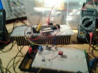
Having acquired a hefty heatsink with which to try out the ZCA and MCA circuits, I decided to try out a higher powered version of my 3 active device amplifier whilst waiting for parts for Marks circuits. If you really wanted to stick with the 2 device topology T2 and T3 could be substituted with a Darlington.
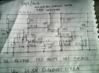
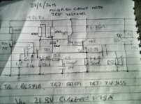
The output as you can see in the diagram is an emitter follower with resistive load. The slightly odd value (7.6 ohm) for the load resistor was arrived at by paralleling 3 of 22 ohm 10 watt resistors, though strictly that should be 7 1/3 ohms, but they are only 10% resistors! (Wirewound VTM ceramic resistors)
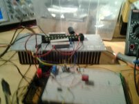
BTW the name hot stuff was inspired by the fact that I burnt my finger on the output resistor whilst working on the circuit! I would recommend you use at least one of those bolt on 50 watt resistors, either 7.5 or 8.2 ohm, you might have to tweak the bias slightly for maximum and symmetrical output swing, note the dissipation of the resistor(s) is nearly 24 watts.
I used the TIP3055 which is in a TO-247 package, instead of the TO-3 Packaged 2n3055, because it suited the heatsink I had and I only had fairly small TO3 style heatsinks. It might be advisable to use the TO3 Transistor as it will run cooler and require a smaller heatsink.
The first stage is a common emitter amplifier, which I had intended to have a gain of only x4, which was fine when I was testing with just the signal generator, however when I hooked it up to my Samsung tablet to provide a source of audio, the gain turned out to be way too low. I tried to bias it properly 15v @ tr1 collector, without the need for a bypass capacitor around the emitter resistor, the original circuit had a 250 ohm emitter resistor and a1k collector resistor giving a gain of 4, this could be biased reliably for 15 volts at the collector. ( The choice of 15 volts was to ensure 13.5 v at the output, that I'd found to be the optimum with 1.75 A standing current and the 7.6 ohm resistor and an 8 ohm load.) Anyway, it turned out that I needed a gain of x34 as the output from the tablet was very low, about 300mv peak to peak maximum, I haven't tried it with a CD player yet, it's downstairs and the workbench is upstairs! I expect I wouldn't need all that gain and could go back to a resistor only at the emitter of tr1.
Another thought and I'd appreciate anyones views on this, is the addition of a resistor either from tr2 emitter to tr3 emitter or from tr2 emitter to ground, someone suggested elsewhere that it would help to linearize tr2 and hence lower distortion.
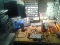
Summary, this was thrown together, see the spaghetti junction layout below, with parts I had lying around as a temporary use for the big heatsink, I didn't expect it to be very good, but I was very surprised, I am sure there are many on here who have heard much better, Best amp I've owened was a Cambridge audio ( I forget which model ), so I can't really claim to be an audiophile ( yet") )
)
I am open to all suggestions for improvement and would enjoy a lively exchange of ideas on this matter.
In summary:
Topology: Single ended Class A with resistive load.
Supply voltage: 22.0 volts @ 1.75 amps.
Output Power: 2.5 w just prior to clipping, about 1.5 watt with no visible distortion on scope.
Gain: X 34 ( 30.6dB )
Sensitivity for max output: 130 mV for 4.45V RMS out.
Distortion: unable to measure.
Output impedance: < 0.2 ohms.
Optimum load: 8 ohms
Output noise: < 1 mV ( that's the lowest I can measure with my meters and the scope has poor noise performance at maximum sensitivity making it hard to measure sub 1 mV levels, I couldn't hear noise in the speaker, but the bench PSU has a noisey fan that makes listening for very quiet sounds difficult, now I know why a lot of you DONT put cooling fans in your amps!
Note this was only a mono prototype.
The 7.6 ohm resistor might not be the perfect choice, it was convenient with the parts I had available, I am open to alternative views on optimum resistor value, bias current and midpoint voltage, and any other thoughts you might have on it, be kind though, it's the first power amp I've designed and shared with the public !
Sorry about the crumby schematic, I'm working on my tablet just now and don't have access to ltspice or tinycad as my laptop is broken.
Having acquired a hefty heatsink with which to try out the ZCA and MCA circuits, I decided to try out a higher powered version of my 3 active device amplifier whilst waiting for parts for Marks circuits. If you really wanted to stick with the 2 device topology T2 and T3 could be substituted with a Darlington.
The output as you can see in the diagram is an emitter follower with resistive load. The slightly odd value (7.6 ohm) for the load resistor was arrived at by paralleling 3 of 22 ohm 10 watt resistors, though strictly that should be 7 1/3 ohms, but they are only 10% resistors! (Wirewound VTM ceramic resistors)
BTW the name hot stuff was inspired by the fact that I burnt my finger on the output resistor whilst working on the circuit! I would recommend you use at least one of those bolt on 50 watt resistors, either 7.5 or 8.2 ohm, you might have to tweak the bias slightly for maximum and symmetrical output swing, note the dissipation of the resistor(s) is nearly 24 watts.
I used the TIP3055 which is in a TO-247 package, instead of the TO-3 Packaged 2n3055, because it suited the heatsink I had and I only had fairly small TO3 style heatsinks. It might be advisable to use the TO3 Transistor as it will run cooler and require a smaller heatsink.
The first stage is a common emitter amplifier, which I had intended to have a gain of only x4, which was fine when I was testing with just the signal generator, however when I hooked it up to my Samsung tablet to provide a source of audio, the gain turned out to be way too low. I tried to bias it properly 15v @ tr1 collector, without the need for a bypass capacitor around the emitter resistor, the original circuit had a 250 ohm emitter resistor and a1k collector resistor giving a gain of 4, this could be biased reliably for 15 volts at the collector. ( The choice of 15 volts was to ensure 13.5 v at the output, that I'd found to be the optimum with 1.75 A standing current and the 7.6 ohm resistor and an 8 ohm load.) Anyway, it turned out that I needed a gain of x34 as the output from the tablet was very low, about 300mv peak to peak maximum, I haven't tried it with a CD player yet, it's downstairs and the workbench is upstairs! I expect I wouldn't need all that gain and could go back to a resistor only at the emitter of tr1.
Another thought and I'd appreciate anyones views on this, is the addition of a resistor either from tr2 emitter to tr3 emitter or from tr2 emitter to ground, someone suggested elsewhere that it would help to linearize tr2 and hence lower distortion.
Summary, this was thrown together, see the spaghetti junction layout below, with parts I had lying around as a temporary use for the big heatsink, I didn't expect it to be very good, but I was very surprised, I am sure there are many on here who have heard much better, Best amp I've owened was a Cambridge audio ( I forget which model ), so I can't really claim to be an audiophile ( yet
)I am open to all suggestions for improvement and would enjoy a lively exchange of ideas on this matter.
In summary:
Topology: Single ended Class A with resistive load.
Supply voltage: 22.0 volts @ 1.75 amps.
Output Power: 2.5 w just prior to clipping, about 1.5 watt with no visible distortion on scope.
Gain: X 34 ( 30.6dB )
Sensitivity for max output: 130 mV for 4.45V RMS out.
Distortion: unable to measure.
Output impedance: < 0.2 ohms.
Optimum load: 8 ohms
Output noise: < 1 mV ( that's the lowest I can measure with my meters and the scope has poor noise performance at maximum sensitivity making it hard to measure sub 1 mV levels, I couldn't hear noise in the speaker, but the bench PSU has a noisey fan that makes listening for very quiet sounds difficult, now I know why a lot of you DONT put cooling fans in your amps!
Note this was only a mono prototype.
The 7.6 ohm resistor might not be the perfect choice, it was convenient with the parts I had available, I am open to alternative views on optimum resistor value, bias current and midpoint voltage, and any other thoughts you might have on it, be kind though, it's the first power amp I've designed and shared with the public !
Sorry about the crumby schematic, I'm working on my tablet just now and don't have access to ltspice or tinycad as my laptop is broken.
Attachments
Last edited:
Something like this?
Simple enough to try since you're still breadboarding.
That's bootstrapping, do you think it would improve performance? Easy enough to try. I have various different class a ideas I want to try out before commiting to a permanent build.
Thanks for your suggestion ballpark.
Thanks jerluwoo, that's what I thought too.
My question is whether a resistor from the emitter of tr2, the driver transistor to ground would help reduce distortion ? This idea was suggested in another thread ( I forget which one )
Also some have suggested that the siziklea ( probably wrong spelling ) pair is better than the Darlington configuration, any thoughts?
Last edited:
A Sziklai pair / CFP would offer the major benefit of considerable local negative feedback and as such presumably much lower distortion (but you might have to watch out for stability concerns). They are quite commonly used for Class A headphone driving with good success.
In your case it would be advisable to turn the circuit upside down with npn<->pnp conversion though, otherwise you'd need a beefy pnp output transistor rather than the npn you are using now. Going pnp for the smaller transistors tends to be a better compromise, as pnps tend to be slower and/or less robust than their npn colleagues.
BTW, your circuit illustrates very nicely why push-pull output stages are the norm in speaker driving.
In a circuit like this using just a single resistor as the pull up device for TR2, it is generally more beneficial to minimize the current draw of the base of TR2. Using your scope you should be able to see that as the circuit swings closer to the positive rail, the wave form becomes more rounded than the negative half. This is caused by the reduction of voltage across the 1k in turn reducing the available turn on current for the base of TR2. This is one thing the bootstrap helps with, but, as always it's a trade off of diffculty in setting an exact gain using just resistance/impedance in the emitter of TR1 and increased noise, etc. etc. Pick your poison.
In a circuit like this using just a single resistor as the pull up device for TR2, it is generally more beneficial to minimize the current draw of the base of TR2. Using your scope you should be able to see that as the circuit swings closer to the positive rail, the wave form becomes more rounded than the negative half. This is caused by the reduction of voltage across the 1k in turn reducing the available turn on current for the base of TR2. This is one thing the bootstrap helps with, but, as always it's a trade off of diffculty in setting an exact gain using just resistance/impedance in the emitter of TR1 and increased noise, etc. etc. Pick your poison.
The first draught of this circuit had an even bigger resistor in the collector of TR1, that was with a very light output stage though, about 250 mA of bias in the output stage. It became apparent that it would need to be much stiffer to drive 1.7 A, hence the value of 1K, the textbook solution would be to use a current source, perhaps? But then you'd probably need to use global negative feedback, yes?
The aim of the circuit was the 'Minimum Component Amplifier' concept suggested by Mark Houston and an integral part of that is no use of global negative feedback, despite what we learn in all the textbooks!
As I said initially, I didn't expect it to sound that good and it took me by surprise.
The output stage is grossly inefficient, for that I make no apology, I had a big heatsink and wanted to use it! Ultimately I don't know if I'd go to the expense of building and boxing this circuit but it is a learning experience.
I am awaiting the arrival of a 2sc5200, do you think this would sound any better than the Tip 3055.
Another plus I forgot to mention is that the bandwidth extends to at least 300 kHz, A1 kHz square wave is almost perfectly reproduced, at the bottom end the emitter bypass cap puts the 3db corner at around 12Hz
It all boils down to accepting the limitations with in your design goal. The best you can do is try to optimize the working point of your devices. Choosing a Vce voltage that will allow the desired output swing with enough extra that it doesn't extend down into the slanted area of the Vce'vs'Ic curves, generally at 2 volts Vce and below. Choosing an idle current where the hfe is 1)Is at or near the maximum for the device, it can be seen when looking at graphs in datasheets that hfe will vary with current. 2) At a point in said graphs where the hfe doesn't change abruptly during the current swing. If you look at a 2n3904 datasheet it can be seen that there is an abrupt drop in hfe above 10mA and below 1mA, choosing a working point that keeps the collector current in between these points will result in less distortion even if it's not at hfe max as in point 1 above. An idle current that keeps the device at or near it's maximum ft, same as with hfe, ft also varies with current. By finding a good compromise of these points will generally give the best overall performance for the chosen device. This should be how operating points are chosen with or with out feedback.
Gross inefficiency is the hallmark of class A SE. It's the first compromise you make when you decide to use it. An emitter follower with passive load as an output stage sounds fantastic. That's just my opinion of coarse.
The 2SC5200 should better the 3055 by a fair margin in gain linearity for considerable reduction in distortion.
Jerluwoo, thanks again for your advice, I will take this stuff on board. I realized there was an issue with HFE changing with varying signal current, not really such an issue with small signal amplifiers but of considerable influence in output stages where the signal swing is considerable and the collector current varies significantly above and below the Q point.
Jerluwoo, where do you stand on the Global negative feedback debate? Mark Houston is clearly inclined toward the Nelson Pass camp, that the tradeoff of lowering distortion with GNFB is nasty unmusical upper harmonics, yet all the electronics books I've read, and I've been reading different ones since primary ( grade ) school say that negative feedback is the panacea for all ills in amplifier circuits!
I was really surprised at how good my amp sounded 'cause in principal its not such a great circuit.
Gordon.
You would get a lot more power using a ccs instead of a 6 ohm resistor for the load.
I agree Woody, but I was working within the remit of the "Minimal Component Amplifier" philosophy from Mark Houston.
See hear for the MCA thread: http://www.diyaudio.com/forums/solid-state/216604-mca-son-zca.html
The essential philosophy is based on the controversial notion that the less active devices in an amplifier the less opportunity there is for the generation of noise and / or distortion, also that the benefits of Global Negative Feedback, is offset by the generation of nasty unmusical upper harmonics instead of the more agreeable 2nd and 3rd order harmonics.
I haven't decided yet where I stand in regards to this standpoint, I'm looking to try out a number of different amp topologies before committing to a permanent build.
Last edited:
Hi,
The 4 transistor JLH from 1969 is a good start for low power
class A amplifier and vastly superior to the 3 transistor above.
Add another transistor for 5 and you can build the "Death of Zen".
Death of Zen - A new Class-A power amp
And you should probably look at :
Minimalist Discrete Hi-Fi Preamp
Main advantage of both is about half the idle supply current and better efficiency.
rgds, sreten.
The 4 transistor JLH from 1969 is a good start for low power
class A amplifier and vastly superior to the 3 transistor above.
An externally hosted image should be here but it was not working when we last tested it.
Add another transistor for 5 and you can build the "Death of Zen".
Death of Zen - A new Class-A power amp
And you should probably look at :
Minimalist Discrete Hi-Fi Preamp
Main advantage of both is about half the idle supply current and better efficiency.
rgds, sreten.
Last edited:
Jerluwoo, where do you stand on the Global negative feedback debate? Mark Houston is clearly inclined toward the Nelson Pass camp, that the tradeoff of lowering distortion with GNFB is nasty unmusical upper harmonics, yet all the electronics books I've read, and I've been reading different ones since primary ( grade ) school say that negative feedback is the panacea for all ills in amplifier circuits!
Gordon.
First I wouldn't say Mr. Pass is against feedback. His commercial offerings as well as the popular diy Aleph's and F5's all use gnf. He knows his devices and how to use them with or without feedback. I would say that many who swear against it are more often than not misguided by the copypasta of single quotes and the like that don't explain what the real issues are. As for the belief that feedback cures all, well a poor design before feedback is still a poor design after feedback. I guess you could say I,m somewhere in the middle, having built and listened to both ends of the spectrum, it's really a matter of what works with your gear(source,speakers,room,etc.) and your ears. Believe what you experience and know to be true and use the available information to guide you along the way, and just enjoy.
You can have a look at the last 2 designs I posted to see that I like the eccentric or odd circuits, both using feedback, both sounding very musical and detailed.
http://www.diyaudio.com/forums/solid-state/266385-fleapower-hybrid.html
http://www.diyaudio.com/forums/headphone-systems/263801-classic-50mw.html
Last edited:
Hi,
The 4 transistor JLH from 1969 is a good start for low power
class A amplifier and vastly superior to the 3 transistor above.
An externally hosted image should be here but it was not working when we last tested it.
Add another transistor for 5 and you can build the "Death of Zen".
Death of Zen - A new Class-A power amp
And you should probably look at :
Minimalist Discrete Hi-Fi Preamp
Main advantage of both is about half the idle supply current and better efficiency.
rgds, sreten.
Thanks sreten, for your suggestions. I have been on Rod Elliot's site before and it is very good for learning, thank you for reminding me.
First I wouldn't say Mr. Pass is against feedback. His commercial offerings as well as the popular diy Aleph's and F5's all use gnf. He knows his devices and how to use them with or without feedback. I would say that many who swear against it are more often than not misguided by the copypasta of single quotes and the like that don't explain what the real issues are. As for the belief that feedback cures all, well a poor design before feedback is still a poor design after feedback. I guess you could say I,m somewhere in the middle, having built and listened to both ends of the spectrum, it's really a matter of what works with your gear(source,speakers,room,etc.) and your ears. Believe what you experience and know to be true and use the available information to guide you along the way, and just enjoy.
You can have a look at the last 2 designs I posted to see that I like the eccentric or odd circuits, both using feedback, both sounding very musical and detailed.
http://www.diyaudio.com/forums/solid-state/266385-fleapower-hybrid.html
http://www.diyaudio.com/forums/headphone-systems/263801-classic-50mw.html
Jerluwoo, perhaps I've been hasty in presuming to understand the intricacies of Mr Pass' work, so far I've only read 2 of his articles and a couple of his circuits.
I do agree with those like yourself who believe their ears and not just the numbers.
I liked your circuits.
Just to clarify my understanding of the first circuit. The triode is the first gain stage, Q2 is configured as a common / grounded base amplifier, yes? This is coupled to Q2, a common emitter amplifier, C5 I presume is to limit the bandwidth for ac stability? The output is an emitter follower using a Darlington npn and a resistive load. C2 provides bootstrapping to increase the gain of Q2 and finally feedback is taken from the junction of the load resistors to the cathode of the triode.
Is that about right, have I missed on any details?
It would be helpful for learners like me if currents and steady state voltages were marked on schematics.
The second one, I think I've seen before but as purely a small signal amplifier, what is the purpose of r5 that's the only thing I was confused about.
Thanks again for everyone's help,
Gordon.
The triode and Q1 form what is called a folded cascode, a technique used for level shifting. R5 in the hp amp is a dc feedback component which helps lock the operating point from any drift. Yes this type of circuit is/was used in mainly preamp and phono amp type circuits. It has low noise and good psrr and works well as a headphone amp.
Last edited:
Jerluwoo, thanks again for your advice, I will take this stuff on board. I realized there was an issue with HFE changing with varying signal current, not really such an issue with small signal amplifiers but of considerable influence in output stages where the signal swing is considerable and the collector current varies significantly above and below the Q point.
Jerluwoo, where do you stand on the Global negative feedback debate? Mark Houston is clearly inclined toward the Nelson Pass camp, that the tradeoff of lowering distortion with GNFB is nasty unmusical upper harmonics, yet all the electronics books I've read, and I've been reading different ones since primary ( grade ) school say that negative feedback is the panacea for all ills in amplifier circuits!
I was really surprised at how good my amp sounded 'cause in principal its not such a great circuit.
Gordon.
Distortion can be pleasant, why don't you make sound effect instead?
Distortion can be pleasant, why don't you make sound effect instead?
Maybe I should make it a guitar amp, class a distortion might be welcome in that application!
The triode and Q1 form what is called a folded cascode, a technique used for level shifting.
Ah, I see it now I've never seen a cascode configured like that, so Q1 doesn't actually produce gain. I presume that Q1 also removes / reduces miller effect in the triode, which otherwise would have swamped the bandwidth given the plate current is so low.
You would get a lot more power using a ccs instead of a 6 ohm resistor for the load.
As it is my speakers have only got 88db / 1 w sensitivity so in reality I'm going to have to build something a bit more powerful. Can any of you explain how I choose the correct idle current when using a CCS load, in order to bet the maximum output power, also I will probably be changing the output transistor to 2sc5200 for better performance.
I also want to try incorporating global negative feedback to make a comparison with the original circuits performance. Any advice would be greatfully received.
I want to thank everyone who has contributed so far to this thread, this is a great learning experience for me and it took a bit of courage to put up what I knew was a far from perfect amplifier, all of your comments, even the critical ones, in fact in particular the critical ones have been illuminating.
Thanks for not slaughtering my first efforts, this has been a very positive experience for me and hope that it continues, my enthusiasm for electronics has been thoroughly rekindled.
Hi,
Just build a DoZ, you wont regret it.
Capacitance Multiplier Power Supply Filter
Go one phase, and further RC decoupling for the preamp.
YMMV but IMHO you can't do better DIY
without shelling out lots more money, as
such I prefer the single supply preamp.
You don't necessarily need the boards,
it can be done with tagstrip layouts.
rgds, sreten.
The DoZ details the best current settings.
Last edited:
- Status
- This old topic is closed. If you want to reopen this topic, contact a moderator using the "Report Post" button.
- Home
- Amplifiers
- Solid State
- Hot stuff- 2w Bipolar Class A Amplifier - A newbies first effort