Hi !
What do you think about texas instrument tipd136 design ?
Active Volume Control for Professional Audio - TIPD136 - TI Tool Folder
I haven't got the knowledge now, but those TI design doc and board files make a very interesting package to start learning and tweaking safely.
Is it worth a try, and lauch a batch of pcbs ?
Am i wrong calculating a input impedance of 68,75k=1/ (1/r6 + 1/r7) ?
Didn't found reference to this design on the forum.
Thanks for help !
The circuit is based on a Peter Baxandall circuit/design/idea from many years ago. I've used these and Doug Self did a similar highly developed design for his 'Precision Preamp' from 1996 and also a later design.
There is some controversy however. You will have to read posts before and after this,
http://www.diyaudio.com/forums/solid-state/209004-new-doug-self-pre-amp-design.html#post2958582
There is some controversy however. You will have to read posts before and after this,
http://www.diyaudio.com/forums/solid-state/209004-new-doug-self-pre-amp-design.html#post2958582
so, let's try it ! 10 pcb batch launched, 9 in swap meet in few weeks/month
Enjoy! I can ask the author (Ian, who sits 15 feet away) if he has one of the boards laying around and I can measure the distortion at lower levels if you're still interested.
It's good to see people are looking at the TI designs docs. We started them with the idea that the traditional app notes of old didn't go far enough. Some of us distrust a circuit unless it's actually been built, put on the bench and run through its paces. If you're going to do all that, you might as well give the reader all of the simulation files, pcb files, and measured data to duplicate your results!
Wow, of course i would be really really interested ! Thanks a lot for this generous offer !
Waiting for result
You're welcome. It's really a selfish offer because right now I'm looking for any excuse I can find to use our new APx555.
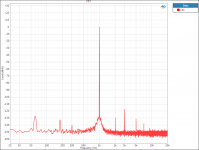
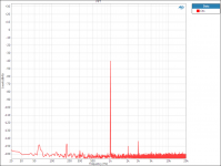
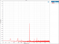
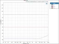
Hey guys, sorry for the slow reply on this. I did some reading on the original thread above to understand Mr. Cordell's concern and found that in that thread the potentiometer used was 1kOhm. I orignally tested the pcb from TIPD136 with a higher impedance potentiometer and didn't see much in the way of distortion, so I ordered a 1kOhm potentiometer and swapped it into the board. I took FFTs of the output signal for a 1kHz sinusoid at 2Vrms. The FFTs are taken at attenuation levels of 0dB, 40dB and 75 dB. The y-axis in these FFTs are dB relative to 2Vrms for ease of comparison. I also measured the frequency response at a these attenuation levels.
For 0dB attenuation and a 2Vrms signal, the 3rd harmonic is dominate at -117dB, the other harmonics are down 130dB or more. At 40dB of attenuation the 3rd harmonic is still dominant and is -103dB below the fundamental. At 75dB of attenuation the 3rd harmonic is 70 dB below the fundamental.
Frequency response only changed in the case of 75dB of attenuation, where there is about a 10dB loss in attenuation at 100kHz.
Overall I feel that if this performance concerns you, a good option would be to use a higher impedance potentiometer.
Attachments
Hey guys, sorry for the slow reply on this.......
Err, not at all. Thank you for running the tests and providing the data so clearly. And these really are worst case results using a 1k pot rather than a somewhat higher value. Even so its pretty decent.
The frequency aberration comes as a surprise to me with what seems a very small increase in attenuation above 1.5kHz or so before the loss you mention. The variation is obviously small though, I'm guessing, perhaps 0.1db or so.
Was the opamp the OPA1604 as mentioned in the pdf ?
The distortion artefacts were of course the main concern and it seems you didn't observe much at all with a higher value pot.
Thanks again John for taking the time to run these tests.
Yes, the op amp tested was the OPA1604. My first guess is that the variation in attenuation for the 75dB case is due to the changing output impedance of the op amp. This effect is somewhat magnified when using a lower impedance potentiometer because the variations in output impedance are a larger percentage of the pot value.
That seems a very plausible theory. I know its a 'half of a quarter of nothing' but good to have an explanation for it non the less. Low impedance circuitry has certainly become a hot topic recently in the quest to push noise levels ever lower. Perhaps in some ways a trade off to far for certain applications.
Thanks again.
Thanks again.
Gosh, I do agree that the App Notes didn't go far enough!
I have a mental image of how they get written in general, which seems to still fit after reading hundreds of them, and it's not that flattering. It goes something like this: Get the newest bod in the company, the one you haven't yet found a role for, and set him the task of writing the app note. He must lack any flair or individualism. else the newbies reading this stuff might not understand the circuit, but he must have some grounding in theory so he can direct the app note away from the component in question while using up space telling us how 1/(s+1) works. He must have no contact with the design team behind the new component, but instead look to previous datasheets to acquaint himself with the house style so that he can bury any innovations in the new product under the achievements that went before. Under no circumstances is he allowed to publish anything either immediately useful, nor in a form in which it can be built and be expected to work. Only the most basic, blunderbuss, circuits will be accepted for publication - except when the product is approaching end-of-life (or there is a competitor) and it needs some sort of fillip to keep interest in it ongoing. At this point, all the clever ideas used by faithful customers over the past decade are to be mercilessly revealed to the general public.
That's just to put a smile on your faces. Thanks Mooly for letting us know from the other thread. I'm sorry to say that I'm not sure especially like this. I'd need to do some more thinking to be sure that my instincts are aligned with reality. I'm all for keeping the pot away from the input but I'm not sure this is the embodiment I'd like to see.
Hey guys, sorry for the slow reply on this. I did some reading on the original thread above to understand Mr. Cordell's concern and found that in that thread the potentiometer used was 1kOhm. I orignally tested the pcb from TIPD136 with a higher impedance potentiometer and didn't see much in the way of distortion, so I ordered a 1kOhm potentiometer and swapped it into the board. I took FFTs of the output signal for a 1kHz sinusoid at 2Vrms. The FFTs are taken at attenuation levels of 0dB, 40dB and 75 dB. The y-axis in these FFTs are dB relative to 2Vrms for ease of comparison. I also measured the frequency response at a these attenuation levels.
For 0dB attenuation and a 2Vrms signal, the 3rd harmonic is dominate at -117dB, the other harmonics are down 130dB or more. At 40dB of attenuation the 3rd harmonic is still dominant and is -103dB below the fundamental. At 75dB of attenuation the 3rd harmonic is 70 dB below the fundamental.
Frequency response only changed in the case of 75dB of attenuation, where there is about a 10dB loss in attenuation at 100kHz.
Overall I feel that if this performance concerns you, a good option would be to use a higher impedance potentiometer.
Nice work, John. Notice that the magnitude of the distortion components is about the same at -40 and -75. This is basically the constant amount of signal-current-induced distortion in the output stage of the op amp. With relatively constant distortion voltage at the output of the op amp, it follows that % distortion will go up as output signal level goes down. What we basically have here is that the output impedance of the op amp is slightly nonlinear.
If the tests were done at a higher fundamental frequency, one would likely see significantly increased THD - probably 10X as much at 10kHz, but I'm just swagging here. I realize that a PC-based distortion measuring setup limited in the highest frequency it can see, may not permit such a test. Alternatively, one could run a 15+16kHz CCIF test and look for IM components in the spectra.
Cheers,
Bob
Since Bob Cordell is here, might I try to enumerate what I think my complaints are about this design - albeit at the risk of seeming like an audio smartarse up against TI/Burr Brown engineers. He would be a good bridge between the two points of view, technical and instinctive perhaps, being able to see both sides.
The first, and maybe not the most important, is that this is an offensive way of doing a 2nd Order low pass filter. Do it properly! I would say that if you have decided you are going to have a buffer then make use of it properly. They say in the notes that it is very hard to work out where this hits its -3dB point (which is not true because it is simply the product of the two filters), then go make a filter that you understand. You can hang a unity gain 2nd Order Butterworth filter around the first op amp and then use the second as just an inverter.
Most importantly, on this topic, who is going to know how this interacts with whatever follows it or precedes it? Thankfully, it is way out at 330kHz, so that sort of hardly matters, but the fact seems to be that it's not even flat at 20kHz, a decade and a half below. I would say that is not ideal design. I am aware that it would be quite nice for noise to have a filter on both op amps, but I'm not even convinced that is what is going on here. Who is to say that the RF doesn't go straight through the parallel C to the output directly. I haven't looked up the GBWP of this particular OPA, but I imagine there is sod all OLG available above 350kHz.
What the ideal is in this instance, I have no idea, but if you really want RF rejection I would say that capacitors to ground are far more reliable. (Common mode chokes are pretty good, too.) And if you want something that will interface with other electronics then the audio bandwidth needs to be perfectly intact. There are a few ways of doing this and higher orders are better. You can actually hang a third order low pass around a single op amp, and that's not out of the way given the range of impedances being used here. You are almost doing it anyway with 3nF and 100pF. Another alternative is, if you must use single order sections (which happens to be a pet hate of mine for reasons I shan't go into here), then put them all at the same frequency. That means that some other part doing the same will get a known (Gaussian) shape of filter, only that its frequency will fall with each additional stage. Lord help you when that gets into the audio band, but it does mean you can daisy-chain one after the other and have something coherent come out. This is very useful for tape loops and so on. In short it is a matter of design "properness" to make sure you know the transfer function of your pre amp.
Four op amps for a volume control is going some. I have done that many with mine, but that included a differential input, a volume control, a 3rd Order low pass and an inverter to give a balanced output. I'd happily go to more, with purpose, but 4 for a single volume control seems lavish to me. Peter Baxandall's original control had two - and I bet he regretted having to use a second. The alternative is simply an inverter with a pot in parallel with the gain resistor (which is one of my preferred ways of doing it). There is a cleverer way that Walt Jung outlines that gives you your balanced input and just one pot on the second op amp, though it's not that conducive to having HF rejection at the input. To go back to my first sentence, four op amps now crashes up against some of the better volume control chips - and they've got I2C to set their level.
I suspect I also detect a flaw in a part of the thinking behind this design. The two sections are mirrors of each other - indeed are identical with 22uF going in and a 100pf feeding back on the second op amp. I presume this is to mimic both sides so that they can sum (or subtract) exactly. But this is not what happens. Assuming I haven't made a mistake in my fairly cursory thinking, the signal to the bottom half has been through two of the 22uF capacitors (and Christ knows it's not needed for any other reason - there's no DC here) and the same at the top. So what is coming out of the bottom two op amps is a second order high pass with a Q of a 1/2 - and likewise an additional roll off at the top end. I don't therefore believe it is achieving what was designed, which was to have a summation of two identical signals, in different quantities, at the output.
Finally, I have a distinct dislike of summing anything except at a virtual ground, whether you have got it right or wrong. The dependencies are so potentially horrible that I have never bothered to examine them in detail - because it is something I would never do. (Bob Cordell will probably point out that I will have done this without knowing on numerous occasions.)
But I humbly submit these as my views (and I'm not against them being shot down at all).
Nice work, John. Notice that the magnitude of the distortion components is about the same at -40 and -75. This is basically the constant amount of signal-current-induced distortion in the output stage of the op amp. With relatively constant distortion voltage at the output of the op amp, it follows that % distortion will go up as output signal level goes down. What we basically have here is that the output impedance of the op amp is slightly nonlinear.
If the tests were done at a higher fundamental frequency, one would likely see significantly increased THD - probably 10X as much at 10kHz, but I'm just swagging here. I realize that a PC-based distortion measuring setup limited in the highest frequency it can see, may not permit such a test. Alternatively, one could run a 15+16kHz CCIF test and look for IM components in the spectra.
Cheers,
Bob
Hi Bob, just to clarify, this isn't a soundcard based PC measurement system. It's an Audio Precision APx555, which is capable of FFTs up to 1MHz. And you're right that the distortion harmonics are most likely increasing at 20dB/dec as the loop gain of the OPA1604 rolls off (35MHz GBW).
But, again, this behavior appears when using a low impedance potentiometer in the circuit (1kOhm) . Isn't this just another example of the design trade-off that often arises between noise performance and distortion performance? For example, what if we changed all the resistors in the circuit to 10 ohms? We would certainly reduce noise, but drastically increase distortion! It's up to the engineer to decide whether noise or distortion performance should be prioritized in their application
ChristianThomas:
I should point out that the idea of using a pot in parallel with the gain resistor of an inverting amplifier will have the same distortion behavior as the Baxandall circuit. You are attenuating the signal while simultaneously increasing the output loading on the op amp.
So...if i understand well :
higher resistance pot => noise,
lower resistance pot => high freq (5-20khz) distortion at low volume ?
Do you know any analog volume design that don't suffer of this kind of impedance/resistance related problem ?
Maybe a more linear (at least it's claimed ?) opamp like lme497xx would have lower distortion ?
Last edited:
All resistors at room temperature generate a noise voltage. The higher the resistor value, the more the noise. If you had a sensitive enough 'scope you could see this white noise just by measuring across a single resistor. The higher the value, the more the voltage present.
Johnson?Nyquist noise - Wikipedia, the free encyclopedia
In audio you have to be realistic. Pushing noise ever lower by using lower values of resistance brings other problems to the fore. Typically the distortion from active circuitry (amplifiers) increases the harder they have to work and so low impedance (low resistance) design means distortion worsens as the amp has to move substantial currents around the low impedance paths.
Going higher in impedance eases the load on the amplifier and so distortion improves, noise however worsens.
Now you have to ask yourself whether the trade off in noise is worthwhile at the expense of distortion. My own opinion is that noise (pure white noise) is the least intrusive of any of the problems an audio system can suffer. I don't mean obvious hiss is acceptable, just that lowering below what is already considered inaudible isn't necessarily the smartest thing to do given that other aspects suffer.
A simple conventional pot used correctly takes some beating from the point of view of sonics. The active control does have a certain elegance to it though and it brings a lot to the table. Perhaps some listening trials of an active vs passive set up at really high attenuation would be interesting. Each stage would be followed by a high gain amp to bring the level back to its nominal starting point.
Yes, i just start to play electronic and try to connect readings (essentially diyaudio + TI/Anolog/Linear technical docs and classic other links like sound.westhost). I've gotten a Tektronix TDS430A so i suppose i could play to see more resistor noise .
My concern about noise is for multieffect instrument preamp, in wich multiple stages add noise. About that, i'm really curious about the boostraped high impedance amplifier http://sound.westhost.com/dwopa.htm, that should be interesting as guitar pickup (20kohm) preamp alternative to classic 1M input resistors. I haven't seen it anywhere.
About distortion, since it's high freq (>5khz) distortion, i tend to think that's not so much a problem if keeped reasonable, since "as far as i've readen", we don't ear so much high frequencies precisely, but more it power content. (sorry for approximative english talking...). And futhermore not a problem at all for instrument electronic (but i play with hifi electronic too).
And add the fact that high distortion of barely audible frequencies is just inaudible (8khz dist > 16khz). If it were mid-low freq it would be a big problem.
. My concern about noise is for multieffect instrument preamp, in wich multiple stages add noise. About that, i'm really curious about the boostraped high impedance amplifier http://sound.westhost.com/dwopa.htm, that should be interesting as guitar pickup (20kohm) preamp alternative to classic 1M input resistors. I haven't seen it anywhere.
About distortion, since it's high freq (>5khz) distortion, i tend to think that's not so much a problem if keeped reasonable, since "as far as i've readen", we don't ear so much high frequencies precisely, but more it power content. (sorry for approximative english talking...). And futhermore not a problem at all for instrument electronic (but i play with hifi electronic too).
And add the fact that high distortion of barely audible frequencies is just inaudible (8khz dist > 16khz). If it were mid-low freq it would be a big problem.
Last edited:
- Status
- This old topic is closed. If you want to reopen this topic, contact a moderator using the "Report Post" button.
- Home
- Source & Line
- Analog Line Level
- TI Active volume control board...tipd136