What are your design goals / priorities besides SE?
Preferably using tube stages, and no interstage transformers, if possible...
I'd like to see teh "archive zip file" mentioned in teh other thread here, but can't access it...
Regards,
John
I'm just tinkering here,,,cost is always the main factor,,, just wanted to see some schematics, and try out teh tube(s)... Here's a schem I may try...
http://www.bonavolta.ch/hobby/images/audio/sv811_1.gif
Regards,
John
http://www.bonavolta.ch/hobby/images/audio/sv811_1.gif
Regards,
John
Please note that the referenced schematic is not using a standard 811A transmitting triode, but a newer Svetlana tube which is not the same... it has no plate cap for starters. A real 811A transmitting tube will not operate in the referenced schematic. As with most transmitting triodes (3C24, 808, 811), you will need to operate them in Class A2 mode (meaning the grid is always positive).
You might want to start with something similar to this:
I-811A.SE
Search around his site... he has several 808/811 amplifiers complete with schematics and measured specifications. The dynamic driver (shown) is a cost-reduced setup, while an interstage transformer would be better albeit more expensive.
Regards, KM
Thank's for teh input,,, thats what I was looking for,,,I'm not into foreign, modern tubes!!! I found a schematic that uses RCA 811s, with a 6L6, and 6SN7, I believe, for teh other stages,,, I was thinking of trying it with a 6BG6 to build a plate cap tube amp!!! I used teh 6BG6s in a 6L6SE amp I've been working on,,, really sounds good so far... Thanks again for teh input,,,Please note that the referenced schematic is not using a standard 811A transmitting triode, but a newer Svetlana tube which is not the same... it has no plate cap for starters. A real 811A transmitting tube will not operate in the referenced schematic. As with most transmitting triodes (3C24, 808, 811), you will need to operate them in Class A2 mode (meaning the grid is always positive).
You might want to start with something similar to this:
I-811A.SE
Search around his site... he has several 808/811 amplifiers complete with schematics and measured specifications. The dynamic driver (shown) is a cost-reduced setup, while an interstage transformer would be better albeit more expensive.
Regards, KM
Regards,
John
Michimori Hirokuni also has some designs, and I think he may be active on this forum too.
Single-ended triode Amps using zero-bias transmitting tubes
Single-ended triode Amps using zero-bias transmitting tubes
Unless you spend a lot of money on an inter-stage the cathode follower or mosfet will always sound better. I have made lots of PP 811A 100 watt amps using 6BL7's as the cathode followers, nothing even comes close. The 811A's last for ever. I have also made SE 811a's, SE, but i think PP has much better sound.
Phil
Phil
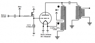
I've had very good results using cathode feedback (CFB) in parallel feed with Tube Lab's Power Drive. To me CFB sounds better than global feedback - YMMV. I have a plate choke wound with a 15% to 25% CFB coil. This is a very flexible setup because you are not stuck with an expensive high end custom transformer if you change your mind. You can always reuse the plate choke and parafeed transformers are less expensive than air gapped series feed transformers.
Attachments
Overall, a nice simple design. One thing to note however... as the 811A is biased with a positive grid voltage, any fluctuation in line voltage will yield a corresponding fluctuation in both plate voltage "and" positive grid voltage. This will result in a rise in plate and grid currents with an increase in line voltage.
When the output tubes are biased with a negative grid voltage, the opposite happens (negative grid voltage increases as well as positive plate voltage) which helps to self regulate static current flow. This is a slight downside for running transmitting type triodes which require positive grid voltage at lower plate supply voltages.
On a 3C24 amp design I did some years ago I used a 5651A voltage reference tube for a regulated positive grid supply to the dynamic driver triode. This results in less drift from line voltage fluctuations and could be a first mod of sorts for the circuit you are showing.
Regards, KM
Overall, a nice simple design. One thing to note however... as the 811A is biased with a positive grid voltage, any fluctuation in line voltage will yield a corresponding fluctuation in both plate voltage "and" positive grid voltage. This will result in a rise in plate and grid currents with an increase in line voltage.
When the output tubes are biased with a negative grid voltage, the opposite happens (negative grid voltage increases as well as positive plate voltage) which helps to self regulate static current flow. This is a slight downside for running transmitting type triodes which require positive grid voltage at lower plate supply voltages.
On a 3C24 amp design I did some years ago I used a 5651A voltage reference tube for a regulated positive grid supply to the dynamic driver triode. This results in less drift from line voltage fluctuations and could be a first mod of sorts for the circuit you are showing.
Regards, KM
Thanks for replying,,, I'm not familiar with teh regulator you mentioned,,, however, I used gas regulators (0C3s) for screen supply in teh 6BG6G SEamp I'm currently working on, they don't fluctuate at all, and teh amp sounds very nice, so far... This one started out as 6L6...
First question I have is why a twin triode is used in what appears to be one channel of a stereo amp, wouldn't a 6J5 in each channel seem a better fit?
Also, the heater supplies seem to only be sized for one channel, as teh 811 heater FT is 4A, which is teh draw of one tube... The driver heater supplies aren't specified, so teh PT can be sized for both channels...
Just thinking out loud, and appreciate the input...
Regards,
John
A 6SN7 won't have enough gain, unless it has a preamp in front of it. The amp will need a small bit of feedback.
An externally hosted image should be here but it was not working when we last tested it.
The 5651A is a voltage reference tube, not a voltage regulator per se. The difference is quite significant actually. The standard range of VR tubes can be used as a shunt regulator, i.e., they have a wide current range (~5ma to 30 or 40ma) which make this possible. The 5651A is intended only to provide a voltage reference which is more stable/quiet than a traditional VR tube. It has a narrow operating range of 1.5ma to 3.5ma and an average voltage of 85 volts.
The 6SN7... it's a choice of the designer/builder... saves a socket in a stereo amp... they were on hand, whatever. More of a moot point.
The 811A filament supply: Would suspect a digital switching regulated supply was used per tube... likely a 6-volt supply which could only be tweaked to 6.2V. You have options.... do the same, use a traditional bridge and large electrolytic caps, get one of Rod's supplies, etc. Whatever you do, don't go with AC as the noise level will likely be unacceptable. Just use separate supplies per output tube.
Yes, you can simply size the power transformer to handle two channels unless you prefer a monoblock layout. I've attached a PDF of my 3C24 amp so you can see how I manage the dynamic driver with variable grid bias via the 5651A reference tube. You may want to adapt this for the 811A.
Regards, KM
Attachments
Artosalas.
Very good circuit.
OUT put impedance of 0.92 ohms is very good, from such a high impedance tube as the 811A
One of the most important measurements, as it gives a good idea of the type of speakers you can use, without getting a lot of boomy bass.
Very few manufacturers, DIYer's ever give the out put impedance.
Phil
Agreed, nice circuit Artosalo,
A bit surprised on the OPT choice as these are somewhat small and have a limited frequency response. I imagine the 811A dwarfs the OPT as well. Still, the performance with NFB is admirable.
In the old days (circa 1950's) Damping Factor (DF) was typically quoted for power amplifiers. In simple terms, it is the ratio of output impedance to (rated) load impedance. The venerable Dyna ST-70's DF was listed as 15, or ~1.07 ohms output impedance (assumimg 16 ohm tap as that's where the feedback loop is taken). Artosalo's 811A amplifier would calculate to a DF of ~8.7. Going with a larger OPT with lower DC resistances on the primary and secondary would improve this somewhat.
Nice to see actual noise measurements as well... which has always been a bit of a pet peeve for me, as most manufacturers (and some DIYers) tend to gloss over specifics of what the reference level is to calculate this. For all amplifiers I design, all specs are done referenced to 1-watt output. Depending on output power, additional specs are done to show headroom and power bandwidth as well.
An example:
1- A 1-watt output into 8 ohms = 2.83 VRMS output level
if your s/n ratio is 80dB (referenced to 1-watt), output noise would be no more than 283 microvolts (0.000283 VRMS).
2- A 100-watt output into 8 ohms = 28.3 VRMS output level
if your s/n ratio is 80dB (referenced to 100-watts), output noise would be no more than 2.83 millivolts (0.00283 VRMS).
This is typically a misleading spec in most ratings, as the 100-watt spec looks good on paper, but is quite noisy in comparison to the 1-watt spec. Normalizing the s/n ratio between the specs, the latter only has a s/n of 60dB.
As Artosalo shows specs with AC filaments on the 811A, the NFB is working hard to quiet things down.... so implementing a proper DC supply would improve this quite a lot as he notes in his spec sheet.
Would like to see a few pics of your amp if they are easily linked")
Regards, KM
A bit surprised on the OPT choice as these are somewhat small and have a limited frequency response. I imagine the 811A dwarfs the OPT as well. Still, the performance with NFB is admirable.
In the old days (circa 1950's) Damping Factor (DF) was typically quoted for power amplifiers. In simple terms, it is the ratio of output impedance to (rated) load impedance. The venerable Dyna ST-70's DF was listed as 15, or ~1.07 ohms output impedance (assumimg 16 ohm tap as that's where the feedback loop is taken). Artosalo's 811A amplifier would calculate to a DF of ~8.7. Going with a larger OPT with lower DC resistances on the primary and secondary would improve this somewhat.
Nice to see actual noise measurements as well... which has always been a bit of a pet peeve for me, as most manufacturers (and some DIYers) tend to gloss over specifics of what the reference level is to calculate this. For all amplifiers I design, all specs are done referenced to 1-watt output. Depending on output power, additional specs are done to show headroom and power bandwidth as well.
An example:
1- A 1-watt output into 8 ohms = 2.83 VRMS output level
if your s/n ratio is 80dB (referenced to 1-watt), output noise would be no more than 283 microvolts (0.000283 VRMS).
2- A 100-watt output into 8 ohms = 28.3 VRMS output level
if your s/n ratio is 80dB (referenced to 100-watts), output noise would be no more than 2.83 millivolts (0.00283 VRMS).
This is typically a misleading spec in most ratings, as the 100-watt spec looks good on paper, but is quite noisy in comparison to the 1-watt spec. Normalizing the s/n ratio between the specs, the latter only has a s/n of 60dB.
As Artosalo shows specs with AC filaments on the 811A, the NFB is working hard to quiet things down.... so implementing a proper DC supply would improve this quite a lot as he notes in his spec sheet.
Would like to see a few pics of your amp if they are easily linked
Regards, KM
- Status
- This old topic is closed. If you want to reopen this topic, contact a moderator using the "Report Post" button.
- Home
- Amplifiers
- Tubes / Valves
- SE 811 amp schematic...