Unit is exhibiting fm tuning issues due to power supply not providing right voltages. In auto, it just scans and in manual it appears that only one channel tunes in, no matter the dialed in value.
I checked voltages on the "Logic Board" and found that CN12 values were 10.5, 12.7, and 30.3 instead of the expected 5.6, 10, and 30. CN28 also is off, giving 12.7 instead of 10. CN11 is giving 10.3 instead of 5.6. CN20 is ok.
Looking at the power supply board, I'm reading bridge D409, 12VAC between the outer legs (~) and 12.7 VDC for the innter (+,-). At fuse F405, 6VAC to Ground. Seems to me the voltage is coming off too high from the bridge (should be 10V?) and something is preventing down-voltage to the required 5.6V. By inspection, is it possible to determine what is causing this?
Attachments
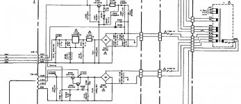
Those would be the likely suspects for failure in this circuit, but do they serve to reduce the voltage? What are those transistors there for? Is this functioning as a voltage regulator such as in:
http://electriciantraining.tpub.com/14179/css/14179_210.htm
Why would one do this in lieu of a voltage regulator such as the lm type?
http://electriciantraining.tpub.com/14179/css/14179_210.htm
Why would one do this in lieu of a voltage regulator such as the lm type?
Last edited:
The transistors make a very simple regulator and ripple filter. The diode produces a stable voltage but the current available is tiny and limited by the two resistors feeding it. To get useful current we apply that voltage to the base of a transistor. That allows the emitter to deliver useful current to our circuit. This particular circuit uses two transistors, one feeding the other for even more current gain. The control input allows the voltage to be shut off (you can't do that with a normal 3 pin reg) when the unit is in standby etc.
So yes, it is a voltage regulator. Three measurements will tell you where the fault is.
1. Voltage across the zener.
2. The voltage across the base and emitter of Q402.
3. The voltage across the base and emitter of Q403.
If either 2 or 3 are above 0.7 ish then the transistor is faulty.
So yes, it is a voltage regulator. Three measurements will tell you where the fault is.
1. Voltage across the zener.
2. The voltage across the base and emitter of Q402.
3. The voltage across the base and emitter of Q403.
If either 2 or 3 are above 0.7 ish then the transistor is faulty.
Great explanation! Exactly what I was looking for!
By coincidence I'm also working on an SX-580 with FM power issues and has same type of voltage regulation, with 2SD712 and 2SC1384 being used (but not cascaded like on the Nak). The SD712, in particular, gets hot and is prone to solder cracking issues.
The TA-4A is showing the same arrangement as for the SR-4A, but with an 2SC1815 instead of the 2SD1406. So commonly used for FM power.
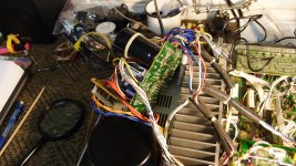
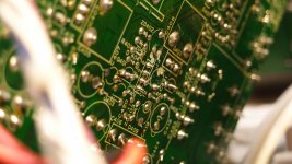
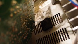
Interesting findings. First pic shows how NAK made it tricky to access the PS board, it cannot be tackled from beneath. Second shows some solder bead issues on C402, the 5.6V power connector, J3, C408, and general area. There was a piece of black foam attached to this area upon dis-assembly. Final pic is a foam pad underneath the PS board. I believe this is the cause of the fault, it has resulted in some conduction between the previously mentioned solder joints. This foam pad has to go. Wonder why it was there to begin with. There is some decent clearance between the pcb and the case.
Voltage across ZD403: 7.03V
Voltage b-e 2SC945 (driver): 4.25V
Voltage b-e 2SD1406: .65V
Since I have the board in the tilted position, I have had no issues on power up. Before, the unit took awhile to come out of protection mode on startup (power light stayed red, now comes green immediately). Either some solder joints are being affected or the foam is also to blame for this problem.
Attachments
Last edited:
Its definitely open circuit with 4 volts across B-E. The 2SC1345 should be OK.
I'm wondering whether its worth replacing the other one too. Those type (generally) have a habit of failing intermittently... I'm wondering if that has happened and that is what has killed the small driver. Any suitable NPN power device would be OK.
Cracked joints are common on any older equipment, particularly around parts that run hot. It can be worth just going over a whole area if there is any suspicion of anything intermittent. The foam is possibly to stop the board being pressed down and shorting... hard to say... but foam, glue, cable ties, all are seen in commercial gear.
As to the original problem... as it is the driver that is zapped, it makes sense in this case to replace both.
I'll replace both. Might also just go ahead and recap the board. The foam is strangely dried out and deteriorated and I'm also seeing possible signs of cap leakage and corrosion. The heat sinks appear to have been glued down and I'm seeing corrosion on the associated transistor leads. I bet the vents were blocked on this thing.
I would initially just try and fix all the faults before doing a general recap etc. That way you know the unit is OK and then if something goes awry with the recap you know where to look. Do too much work, and then hit a problem and its more difficult finding what went wrong.
Couldn't it just be a case of bad soldering of the transistor?
I've encountered a few cases where the soldering on a visual inspection looked just fine, but must have had a layer of oxidation between the circuit trace and solder.
(dunno if I makes sense, English is not my native language.)
I've encountered a few cases where the soldering on a visual inspection looked just fine, but must have had a layer of oxidation between the circuit trace and solder.
(dunno if I makes sense, English is not my native language.)
Couldn't it just be a case of bad soldering of the transistor?
I've encountered a few cases where the soldering on a visual inspection looked just fine, but must have had a layer of oxidation between the circuit trace and solder.
(dunno if I makes sense, English is not my native language.)
Unlikely given the high output voltage of the reg. Only a dry on the zener could give the raised output voltage. One damaging scenario is where a dry on the collector of the series pass device would see the driver trying to supply all the current via the B-E junction of the pass device.
Oxidation of component leads is a real problem. When you reflow the joints the solder doesn't "take".
Your English is perfect
")
KSC945(C) or you will have to do some origami folding with the legs
(C) as in center collector.
Good point!
Got the new parts in. Q402 was confirmed defective. Q402, Q403, and ZD403 replaced. I am now getting 5.6V on CN12 which is correct (I was getting 10V before), but I'm reading 13.9V instead of 10V on this connector. This fault was also present before repair, but I thought it would also be corrected with replacement of Q402. I believe it is causing the issues I'm experiencing on the tuner. No AM at all, and on FM, signal meter is stuck on 3 lights and only one station comes in no matter the tuning position. TP1 is reading .5V (should be 20mV) and TP2 is reading 6V (should be 22V). I am at a loss as to why I'm getting 13.9V instead of 10V at CN12.
- Status
- This old topic is closed. If you want to reopen this topic, contact a moderator using the "Report Post" button.
- Home
- Amplifiers
- Power Supplies
- Power Issues Nakamichi SR-4A