Hi friends,
i am using sanyo 4400 IC's kit. the kit had no instruction manual and the vendor had no idea how to use the kit... can anyone please help me find that what the marked spacers used for in the circuit? i'd be really thankful")
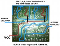
(strange irony pin number 11 which is vcc has been left blank in the circuit.. how am i supposed to give voltage to it? or do the ic have to be soldered facing away from the board so that pin number 11 actually becomes pin number 4 and vice versa?)
i am using sanyo 4400 IC's kit. the kit had no instruction manual and the vendor had no idea how to use the kit... can anyone please help me find that what the marked spacers used for in the circuit? i'd be really thankful
(strange irony pin number 11 which is vcc has been left blank in the circuit.. how am i supposed to give voltage to it? or do the ic have to be soldered facing away from the board so that pin number 11 actually becomes pin number 4 and vice versa?)
An externally hosted image should be here but it was not working when we last tested it.
An externally hosted image should be here but it was not working when we last tested it.
Here is a guess work from me .
Please double check
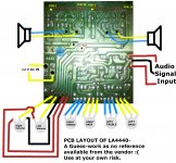
Pin 10and 12 are for out put via 1000uFd e-caps as per datasheet.
May be you need to a a Filter cap to the circuit at c19 too if you notice any hum.
All the very best.
Please double check
Pin 10and 12 are for out put via 1000uFd e-caps as per datasheet.
May be you need to a a Filter cap to the circuit at c19 too if you notice any hum.
All the very best.
Attachments
Last edited:
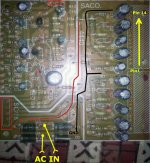
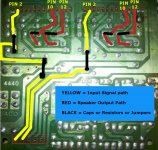
The 3 points which you have marked red might be for signal input as they are connected to input Electrolytic caps with a biasing of 15k to the buffer amp using transistors I guess .
Upon first power up you can check them by touching at the input with a screw driver .
Upon first power up you can check them by touching at the input with a screw driver .
Last edited:
The 3 points which you have marked red might be for signal input as they are connected to input Electrolytic caps with a biasing of 15k to the buffer amp using transistors I guess .
Upon first power up you can check them by touching at the input with a screw driver .
according to datasheet input is pin number 2 which is directly connected from the first pin in the board(5 empty connectors)
thank you csom for sharing your valuable knowledge! why are the transistors used? a minor pre-amp?
You are more than most welcome
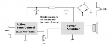
Usually this type of amp kits uses a bass and treble control. So I presume these two transistors are used here as buffer amplifiers.
And regarding the number of passive components there might be bass and treble controls too. I will look more and post my observation
You are more than most welcome
Usually this type of amp kits uses a bass and treble control. So I presume these two transistors are used here as buffer amplifiers.
And regarding the number of passive components there might be bass and treble controls too. I will look more and post my observation
also, pardon me, but according to you, pin number 10-12 should give the output but both of them after being filtered are getting short to the rail in between the circuit connecting to diode d1-d2.. this is very confusing...
Well, after a lot of hammering on the brain, this is my personal observation.
Use it at your own risk.
Two cents more:
1. Connect the wires, Speakers, Potentiometers, Heat Sinks etc.
2. Get a small 9v battery and a switch.
3. Power it up with the battery for some seconds only and touch both the input one by one very quickly.
4. If you get any low humming or buzzing noise from the speakers, that's a good sign and you may go ahead with AC power testing.
I always do my first power up adding a Lamp in series with the AC Mains Transformer.
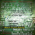
5. Last but not the least, I am missing a good filter cap in the board from your photos. So I marked a Blue Circle with polarity. An Electrolytic cap with 2200 Ufd 25V (warning: with correct polarity) is a good value to start with for ripple filter, I guess.
If it works, kindly post your feedback.
Best of luck.
Use it at your own risk.
Two cents more:
1. Connect the wires, Speakers, Potentiometers, Heat Sinks etc.
2. Get a small 9v battery and a switch.
3. Power it up with the battery for some seconds only and touch both the input one by one very quickly.
4. If you get any low humming or buzzing noise from the speakers, that's a good sign and you may go ahead with AC power testing.
I always do my first power up adding a Lamp in series with the AC Mains Transformer.
5. Last but not the least, I am missing a good filter cap in the board from your photos. So I marked a Blue Circle with polarity. An Electrolytic cap with 2200 Ufd 25V (warning: with correct polarity) is a good value to start with for ripple filter, I guess.
If it works, kindly post your feedback.
Best of luck.
Attachments
Last edited:
also, pardon me, but according to you, pin number 10-12 should give the output but both of them after being filtered are getting short to the rail in between the circuit connecting to diode d1-d2.. this is very confusing...
Please double check.
Here is what I figured out.
Attachments
Hi friends,
i am using sanyo 4400 IC's kit. .........
Err..., is it by mistake that you wrote 4400? I guess it would be 4440 as it is printed on the board.
thank you mr csom! can you just answer my one last query? can the circuit work without connecting bass-treble pot controls?
Sure the circuit can work without Bass and treble pot Control. But I would prefer small variable resistors in place of them to obtain proper gain.
Any way you can experiement later on.
Last edited:
- Status
- This old topic is closed. If you want to reopen this topic, contact a moderator using the "Report Post" button.
- Home
- Amplifiers
- Chip Amps
- Need help with 4400 ic pinouts